 |
データシートサーチシステム |
|
|
データシートサーチシステム |
|
The question interval is too short.
Please try again in a few seconds.

Hello, Please ask a question about T1020-600W Datasheet
# Example questions:
➢ What is the typical value for dimension l2 in millimeters?
➢ What is the maximum allowable value for dimension 'h' in inches?
➢ What is the typical value for dimension 'diam' in millimeters?
| Part No. | T1020-600W |
| Manufacturer | STMICROELECTRONICS |
| Size | 119 Kbytes |
| Pages | 5 pages |
| Description | SNUBBERLESS TRIAC |


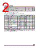
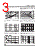
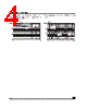


1. General Information & Key Parameters:
️· Device Type: TRIAC (Triode for Alternating Current) - A semiconductor device that acts as an electronically controlled switch for AC circuits.
️· Voltage Ratings: Specifies the maximum voltage the TRIAC can handle (VDRM, VRRM, VTM).
️· Current Ratings: Specifies the maximum current the TRIAC can conduct (ITM, IRM, ISM).
️· Isolation Voltage: The voltage the TRIAC can withstand without breaking down between its terminals and its case.
️· Commutation Time: How quickly the TRIAC switches between conducting and non-conducting states.
️· Gate Trigger Parameters: Specifies how much current or voltage is needed to turn the TRIAC on.
️· Thermal Resistance: How effectively heat is dissipated from the TRIAC. Important for preventing overheating and failure.
2. Electrical Characteristics Tables:
These tables provide the specific electrical performance of the TRIAC under various conditions. Key parameters include:
️· VDRM/VRRM (Repetitive Peak Off-State Voltage): The maximum repetitive voltage the TRIAC can block in the off-state.
️· ITM (On-State Current): The maximum current the TRIAC can carry while fully conducting.
️· HTM (Holding Current): The minimum current required to maintain conduction after the gate trigger signal is removed.
️· IGT (Gate Trigger Current): The current needed at the gate to turn the TRIAC on.
️· VGT (Gate Trigger Voltage): The voltage needed at the gate to turn the TRIAC on.
️· Dynamic Parameters: Parameters related to switching speed and behavior.
3. Waveforms and Characteristics Curves:
These graphs illustrate the relationship between different electrical parameters and help understand how the TRIAC behaves under various operating conditions. For example, you might see curves showing how on-state voltage varies with current, or how gate trigger current changes with temperature.
4. Absolute Maximum Ratings:
This section lists the absolute limits for various parameters. Exceeding these limits can permanently damage the TRIAC.
5. Operating Characteristics:
This section is similar to the absolute maximum ratings but presents typical values under specific conditions.
6. Thermal Considerations
This portion of the datasheet includes info about how the device dissipates heat. It includes Thermal resistance junction-to-case, junction-to-ambient and provides information for thermal management of the component.
7. Number of cycles for I2t curve and maximum surge current.
8. Mechanical Dimensions:
The final section provides detailed mechanical drawings of the TRIAC package, including dimensions in both millimeters and inches. This is essential for PCB layout and ensuring the device fits correctly in your circuit.
In summary, this datasheet is a comprehensive reference for engineers and designers who need to use this TRIAC in their applications. It provides all the necessary information to select the right device, design a proper circuit, and ensure reliable operation.
1. General Information & Key Parameters:
️· Device Type: TRIAC (Triode for Alternating Current) - A semiconductor device that acts as an electronically controlled switch for AC circuits.
️· Voltage Ratings: Specifies the maximum voltage the TRIAC can handle (VDRM, VRRM, VTM).
️· Current Ratings: Specifies the maximum current the TRIAC can conduct (ITM, IRM, ISM).
️· Isolation Voltage: The voltage the TRIAC can withstand without breaking down between its terminals and its case.
️· Commutation Time: How quickly the TRIAC switches between conducting and non-conducting states.
️· Gate Trigger Parameters: Specifies how much current or voltage is needed to turn the TRIAC on.
️· Thermal Resistance: How effectively heat is dissipated from the TRIAC. Important for preventing overheating and failure.
2. Electrical Characteristics Tables:
These tables provide the specific electrical performance of the TRIAC under various conditions. Key parameters include:
️· VDRM/VRRM (Repetitive Peak Off-State Voltage): The maximum repetitive voltage the TRIAC can block in the off-state.
️· ITM (On-State Current): The maximum current the TRIAC can carry while fully conducting.
️· HTM (Holding Current): The minimum current required to maintain conduction after the gate trigger signal is removed.
️· IGT (Gate Trigger Current): The current needed at the gate to turn the TRIAC on.
️· VGT (Gate Trigger Voltage): The voltage needed at the gate to turn the TRIAC on.
️· Dynamic Parameters: Parameters related to switching speed and behavior.
3. Waveforms and Characteristics Curves:
These graphs illustrate the relationship between different electrical parameters and help understand how the TRIAC behaves under various operating conditions. For example, you might see curves showing how on-state voltage varies with current, or how gate trigger current changes with temperature.
4. Absolute Maximum Ratings:
This section lists the absolute limits for various parameters. Exceeding these limits can permanently damage the TRIAC.
5. Operating Characteristics:
This section is similar to the absolute maximum ratings but presents typical values under specific conditions.
6. Thermal Considerations
This portion of the datasheet includes info about how the device dissipates heat. It includes Thermal resistance junction-to-case, junction-to-ambient and provides information for thermal management of the component.
7. Number of cycles for I2t curve and maximum surge current.
8. Mechanical Dimensions:
The final section provides detailed mechanical drawings of the TRIAC package, including dimensions in both millimeters and inches. This is essential for PCB layout and ensuring the device fits correctly in your circuit.
In summary, this datasheet is a comprehensive reference for engineers and designers who need to use this TRIAC in their applications. It provides all the necessary information to select the right device, design a proper circuit, and ensure reliable operation.
| Part No. | T1020-600W |
| Manufacturer | STMICROELECTRONICS |
| Size | 119 Kbytes |
| Pages | 5 pages |
| Description | SNUBBERLESS TRIAC |
| ALLDATASHEETはお客様のビジネスに役立ちますか? [ DONATE ] |
Alldatasheetは | 広告 | お問い合わせ | プライバシーポリシー | データシートへのリンク | リンク交換 | メーカーリスト All Rights Reserved©Alldatasheet.com |
| Russian : Alldatasheetru.com | Korean : Alldatasheet.co.kr | Spanish : Alldatasheet.es | French : Alldatasheet.fr | Italian : Alldatasheetit.com Portuguese : Alldatasheetpt.com | Polish : Alldatasheet.pl | Vietnamese : Alldatasheet.vn Indian : Alldatasheet.in | Mexican : Alldatasheet.com.mx | British : Alldatasheet.co.uk | New Zealand : Alldatasheet.co.nz |
|
Family Site : ic2ic.com |
icmetro.com |
 Japanese ▼
  English
 Chinese
 German
 Russian
 Korean
 Spanish
 French
 Italian
 Portuguese
 Polish
 Vietnamese
 Indian
 Mexican
 British
 New Zealand