 |
データシートサーチシステム |
|
|
データシートサーチシステム |
|
The question interval is too short.
Please try again in a few seconds.

Hello, Please ask a question about MSTM-S3-TR-16019.44M Datasheet
# Example questions:
➢ What is this peak current, and which pins should be planned for this requirement?
➢ What is the board space required for the mstm-s3-tr module?
➢ What is the recommended hole diameter for the pins to facilitate easy insertion and rework?
| Part No. | MSTM-S3-TR-16019.44M |
| Manufacturer | CONNOR-WINFIELD |
| Size | 1Mb |
| Pages | 16 pages |
| Description | Stratum 3 Timing Module |








Document Overview
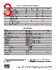
This document is an excerpt from a technical datasheet (Data Sheet #TM027, Revision 05, Date 12/02/02) for a component called the "MSTM-S3-TR." It provides details on the product's mechanical specifications, electrical considerations, soldering/cleaning recommendations, and a general outline. It seems geared towards engineers or technicians responsible for integrating this component into a larger system. The document covers pages 10-14.
1. Timing Diagrams & Performance (Implied, but limited information)
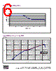
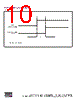
️· Loss of Reference Timing Diagram: (Figure 13) Details on how the system behaves when it loses its reference signal are provided (but not described in the text itself).
️· Power-on Reset Levels: (Figure 14) Shows power states during startup.
️· Characteristic Measurements: (Table 6) shows measurements such as Pad-to-Pad Spacing, Diameter of Solder pads, and Pin row spacing
2. Mechanical Specifications & Layout
️· Overall Dimensions: The module is 2" x 2".
️· Pin Details: Pins are 0.040" diameter, 0.150" length, with 0.030" shoulders for standoff.
️· Pad Array: Dual-in-line pin configuration.
️· Pad Spacing: 0.2" in-line, 1.6" between rows.
️· Recommended Pad Construction: Suggested hole diameter of 0.055" for insertion, pad diameter of 0.150" for support.
️· Solder Mask: Solder mask recommended to cover most of the top pad.
️· Via Keep Out Area: No vias or feedthroughs underneath the module body.
3. Electrical Considerations
️· Power Supply:
- OCXO (Ovenized Crystal Oscillator) may be incorporated for wider temperature ranges (0 to 70 °C).
- OCXO turn-on current: peak ~0.4A for ~1 minute.
- Steady-state current: 50-150 mA (depending on temperature).
- Power supply regulation recommended: 4.75 - 5.25 volts, avoids wander.
- Pins 18 & 5 are for peak current. Pins 10, 12, 14, and 16 are for signal ground.
️· Soldering Recommendations: Hand soldering or wave soldering post-reflow.
4. Handling & Cleaning
️· Cleaning: Hand cleaning after soldering is preferred. Avoid full immersion.
️· Bakout: Do not bake out the module.
5. Package Dimensions
️· Figure 16 provides dimensions of the Module and Figure 17 provides Footprint dimension
Key Takeaways/Important Notes
️· Power Supply: Careful attention to power supply regulation and peak current handling is crucial.
️· Mechanical Integrity: The mechanical layout details are designed to facilitate insertion, rework, and protect sensitive components.
️· Handling Precautions: The component is sensitive, and strict adherence to cleaning and baking recommendations is essential.
️· Context Dependent: The use of OCXO depends on the operating temperature range.
Disclaimer: This summary is based solely on the provided text snippets and might not represent the complete functionality or specifications of the MSTM-S3-TR. Consult the complete datasheet for comprehensive details.
Document Overview
This document is an excerpt from a technical datasheet (Data Sheet #TM027, Revision 05, Date 12/02/02) for a component called the "MSTM-S3-TR." It provides details on the product's mechanical specifications, electrical considerations, soldering/cleaning recommendations, and a general outline. It seems geared towards engineers or technicians responsible for integrating this component into a larger system. The document covers pages 10-14.
1. Timing Diagrams & Performance (Implied, but limited information)
️· Loss of Reference Timing Diagram: (Figure 13) Details on how the system behaves when it loses its reference signal are provided (but not described in the text itself).
️· Power-on Reset Levels: (Figure 14) Shows power states during startup.
️· Characteristic Measurements: (Table 6) shows measurements such as Pad-to-Pad Spacing, Diameter of Solder pads, and Pin row spacing
2. Mechanical Specifications & Layout
️· Overall Dimensions: The module is 2" x 2".
️· Pin Details: Pins are 0.040" diameter, 0.150" length, with 0.030" shoulders for standoff.
️· Pad Array: Dual-in-line pin configuration.
️· Pad Spacing: 0.2" in-line, 1.6" between rows.
️· Recommended Pad Construction: Suggested hole diameter of 0.055" for insertion, pad diameter of 0.150" for support.
️· Solder Mask: Solder mask recommended to cover most of the top pad.
️· Via Keep Out Area: No vias or feedthroughs underneath the module body.
3. Electrical Considerations
️· Power Supply:
- OCXO (Ovenized Crystal Oscillator) may be incorporated for wider temperature ranges (0 to 70 °C).
- OCXO turn-on current: peak ~0.4A for ~1 minute.
- Steady-state current: 50-150 mA (depending on temperature).
- Power supply regulation recommended: 4.75 - 5.25 volts, avoids wander.
- Pins 18 & 5 are for peak current. Pins 10, 12, 14, and 16 are for signal ground.
️· Soldering Recommendations: Hand soldering or wave soldering post-reflow.
4. Handling & Cleaning
️· Cleaning: Hand cleaning after soldering is preferred. Avoid full immersion.
️· Bakout: Do not bake out the module.
5. Package Dimensions
️· Figure 16 provides dimensions of the Module and Figure 17 provides Footprint dimension
Key Takeaways/Important Notes
️· Power Supply: Careful attention to power supply regulation and peak current handling is crucial.
️· Mechanical Integrity: The mechanical layout details are designed to facilitate insertion, rework, and protect sensitive components.
️· Handling Precautions: The component is sensitive, and strict adherence to cleaning and baking recommendations is essential.
️· Context Dependent: The use of OCXO depends on the operating temperature range.
Disclaimer: This summary is based solely on the provided text snippets and might not represent the complete functionality or specifications of the MSTM-S3-TR. Consult the complete datasheet for comprehensive details.
| Part No. | MSTM-S3-TR-16019.44M |
| Manufacturer | CONNOR-WINFIELD |
| Size | 1Mb |
| Pages | 16 pages |
| Description | Stratum 3 Timing Module |
| ALLDATASHEETはお客様のビジネスに役立ちますか? [ DONATE ] |
Alldatasheetは | 広告 | お問い合わせ | プライバシーポリシー | データシートへのリンク | リンク交換 | メーカーリスト All Rights Reserved©Alldatasheet.com |
| Russian : Alldatasheetru.com | Korean : Alldatasheet.co.kr | Spanish : Alldatasheet.es | French : Alldatasheet.fr | Italian : Alldatasheetit.com Portuguese : Alldatasheetpt.com | Polish : Alldatasheet.pl | Vietnamese : Alldatasheet.vn Indian : Alldatasheet.in | Mexican : Alldatasheet.com.mx | British : Alldatasheet.co.uk | New Zealand : Alldatasheet.co.nz |
|
Family Site : ic2ic.com |
icmetro.com |
 Japanese ▼
  English
 Chinese
 German
 Russian
 Korean
 Spanish
 French
 Italian
 Portuguese
 Polish
 Vietnamese
 Indian
 Mexican
 British
 New Zealand