 |
データシートサーチシステム |
|
|
データシートサーチシステム |
|
The question interval is too short.
Please try again in a few seconds.

Hello, Please ask a question about AD7828BRS Datasheet
# Example questions:
➢ What is the primary function of the ad7824 and ad7828?
➢ What are two key benefits of the ad7824/ad7828 highlighted in the document, relating to system design and performance?
➢ What digital signals are required to interface with the ad7824/ad7828?
| Part No. | AD7828BRS |
| Manufacturer | AD |
| Size | 270 Kbytes |
| Pages | 16 pages |
| Description | LC2MOS High Speed 4- & 8-Channel 8-Bit ADCs |


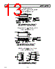


Okay, let's break down what we have here. This appears to be an excerpt from a data sheet for a mixed-signal product – specifically, a multiplexed Analog-to-Digital Converter (ADC) system, likely the AD7824 or AD7828. Here’s a summary, breaking it down into key points and explaining the technical terms where relevant:
1. Product Overview:
️· AD7824 & AD7828: These are two versions of a product – both are ADC systems, but the AD7828 has more channels (8 vs. 4 for the AD7824). They's built around a multiplexer, meaning they can switch between multiple analog input signals and feed them one at a time to an ADC.
2. Key Features & Highlights (and explanations):
️· Multiplexed Input: This is the core of the product. "Multiplexing" means that the ADC can read from multiple analog inputs, switching between them sequentially. This saves space and reduces component count compared to having individual ADCs for each channel.
️· Conversion Rate: "2.5 µs/channel" means it takes 2.5 microseconds to convert each channel to a digital value. Faster conversion is generally better.
️· Sampling Frequency: The sampling frequency (100 kHz for the AD7824 and 50 kHz for AD7828) indicates how often the system can take a reading from each channel. Higher is generally better.
️· Track-and-Hold (T&H): This is a circuit that "samples" the analog signal at a specific point in time and holds that value. This is critical for accurate conversions when the input signal is changing quickly. The 10 kHz bandwidth and 157 mV/µs slew rate tell you the limits of how fast-changing signals the T&H can handle accurately. Slew rate refers to how quickly the voltage can change.
️· Total Unadjusted Error: Indicates accuracy and consistency across channels. Lower values mean better performance and reduced need for user calibration.
️· Single 5V Supply: Means the system is powered by a simple 5-volt supply, making it easier to integrate into a circuit.
️· Digital Interface: A connection that allows the analog signal to be converted to digital data. "No clock signal required" means the interface is simpler to implement.
3. Product Specification:
️· RDY, CS, RD: These are likely control signals used to manage the ADC operation. (RDY = Ready, CS = Chip Select, RD = Read).
In essence, this document describes a convenient, relatively high-speed, and accurate system for digitizing signals from multiple analog sources.
1. Product Overview:
️· AD7824 & AD7828: These are two versions of a product – both are ADC systems, but the AD7828 has more channels (8 vs. 4 for the AD7824). They's built around a multiplexer, meaning they can switch between multiple analog input signals and feed them one at a time to an ADC.
2. Key Features & Highlights (and explanations):
️· Multiplexed Input: This is the core of the product. "Multiplexing" means that the ADC can read from multiple analog inputs, switching between them sequentially. This saves space and reduces component count compared to having individual ADCs for each channel.
️· Conversion Rate: "2.5 µs/channel" means it takes 2.5 microseconds to convert each channel to a digital value. Faster conversion is generally better.
️· Sampling Frequency: The sampling frequency (100 kHz for the AD7824 and 50 kHz for AD7828) indicates how often the system can take a reading from each channel. Higher is generally better.
️· Track-and-Hold (T&H): This is a circuit that "samples" the analog signal at a specific point in time and holds that value. This is critical for accurate conversions when the input signal is changing quickly. The 10 kHz bandwidth and 157 mV/µs slew rate tell you the limits of how fast-changing signals the T&H can handle accurately. Slew rate refers to how quickly the voltage can change.
️· Total Unadjusted Error: Indicates accuracy and consistency across channels. Lower values mean better performance and reduced need for user calibration.
️· Single 5V Supply: Means the system is powered by a simple 5-volt supply, making it easier to integrate into a circuit.
️· Digital Interface: A connection that allows the analog signal to be converted to digital data. "No clock signal required" means the interface is simpler to implement.
3. Product Specification:
️· RDY, CS, RD: These are likely control signals used to manage the ADC operation. (RDY = Ready, CS = Chip Select, RD = Read).
In essence, this document describes a convenient, relatively high-speed, and accurate system for digitizing signals from multiple analog sources.
| Part No. | AD7828BRS |
| Manufacturer | AD |
| Size | 270 Kbytes |
| Pages | 16 pages |
| Description | LC2MOS High Speed 4- & 8-Channel 8-Bit ADCs |
| ALLDATASHEETはお客様のビジネスに役立ちますか? [ DONATE ] |
Alldatasheetは | 広告 | お問い合わせ | プライバシーポリシー | データシートへのリンク | リンク交換 | メーカーリスト All Rights Reserved©Alldatasheet.com |
| Russian : Alldatasheetru.com | Korean : Alldatasheet.co.kr | Spanish : Alldatasheet.es | French : Alldatasheet.fr | Italian : Alldatasheetit.com Portuguese : Alldatasheetpt.com | Polish : Alldatasheet.pl | Vietnamese : Alldatasheet.vn Indian : Alldatasheet.in | Mexican : Alldatasheet.com.mx | British : Alldatasheet.co.uk | New Zealand : Alldatasheet.co.nz |
|
Family Site : ic2ic.com |
icmetro.com |
 Japanese ▼
  English
 Chinese
 German
 Russian
 Korean
 Spanish
 French
 Italian
 Portuguese
 Polish
 Vietnamese
 Indian
 Mexican
 British
 New Zealand