 |
データシートサーチシステム |
|
|
データシートサーチシステム |
|
The question interval is too short.
Please try again in a few seconds.

Hello, Please ask a question about AP3785T Datasheet
# Example questions:
➢ How does the implementation of multiple segment peak current control (described in section 5) help to address potential audible noise issues in the power system?
➢ Explain how the ap3785t achieves constant current (cc) mode operation, referencing equation (2) and (3) from the document.
➢ What is the primary function of the auxiliary winding in the flyback converter?
| Part No. | AP3785T |
| Manufacturer | DIODES |
| Size | 659 Kbytes |
| Pages | 18 pages |
| Description | PRIMARY SIDE REGULATED SWITCHING MODE POWER SUPPLY CONTROLLER |


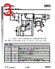

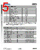

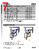
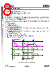


1. Overview & Functionality (Flyback Converter)
️· Purpose: The AP3785T is designed for use in a flyback converter power supply. Flyback converters are common for isolated power supplies (providing both voltage isolation and voltage conversion).
️· 3-Winding Transformer: The converter uses a transformer with three windings:
- Primary (N P ): Receives input power.
- Secondary (N S ): Provides power to the load.
- Auxiliary (N AUX ): Provides power to the IC itself (VCC) and generates a voltage feedback signal to the FB pin.
️· Isolation: The flyback topology inherently provides galvanic isolation between the input and output.
2. Operating Modes
️· Constant Voltage (CV) Mode:
- Feedback Control: The IC monitors the voltage at the auxiliary winding (using the FB pin) and regulates the output voltage.
- Multi-Segment Peak Current Control: A key feature for noise reduction. The converter uses different peak current levels based on load:
■ V CS_H: High load
■ V CS_M: Medium Load
■ V CS_L: Light Load
- Segmented Frequency: The switching frequency changes based on the load and current segment to maintain efficiency and reduce noise.
️· Constant Current (CC) Mode:
- Fixed Duty Cycle: Maintains a fixed relationship between the on-time and off-time of the switching element.
- Output Current Control: Provides a constant output current.
- Peak Current Sensing: Uses current reference V CS_H
️· No Load/Ultra Light Load (NL) Mode: Specific operation for very light loads, details of which are briefly mentioned but not elaborated.
3. Key Control Strategies & Parameters
️· Peak Current Sensing:
- The primary current (ip(t)) is sensed using a current sense resistor (R CS).
- The peak current (I PK) is proportional to the input voltage (V IN), the inductance (L), and the sense resistor value.
️· Output Voltage Regulation (CV Mode):
- The auxiliary winding voltage (V AUX) is monitored via the FB pin.
- The control loop adjusts the peak current to maintain the desired output voltage.
️· Switching Frequency Adjustment:
- The IC adjusts the switching frequency to optimize efficiency and reduce noise based on the peak current segment selected.
️· Duty Cycle Control (CC Mode):
- The duty cycle (tON/tOFF) is fixed to maintain a constant output current.
4. Equations (Key Relationships)
️· Peak Current: `I PK = (V IN * t) / L`
️· Output Voltage Regulation: `V AUX = N AUX * (V OUT + Vd) / N S`
️· Duty Cycle (CC Mode): `tON / tOFF = constant`
️· Energy Stored in Magnetizing Inductance: `Eg = (1/2) * L * I^2`
Key takeaways:
️· The AP3785T is a versatile controller for flyback converters.
️· The multi-segment current control and adjustable switching frequency are crucial for efficient and low-noise operation across a wide range of load conditions.
️· The controller provides both constant voltage and constant current modes, expanding its application versatility.
1. Overview & Functionality (Flyback Converter)
️· Purpose: The AP3785T is designed for use in a flyback converter power supply. Flyback converters are common for isolated power supplies (providing both voltage isolation and voltage conversion).
️· 3-Winding Transformer: The converter uses a transformer with three windings:
- Primary (N P ): Receives input power.
- Secondary (N S ): Provides power to the load.
- Auxiliary (N AUX ): Provides power to the IC itself (VCC) and generates a voltage feedback signal to the FB pin.
️· Isolation: The flyback topology inherently provides galvanic isolation between the input and output.
2. Operating Modes
️· Constant Voltage (CV) Mode:
- Feedback Control: The IC monitors the voltage at the auxiliary winding (using the FB pin) and regulates the output voltage.
- Multi-Segment Peak Current Control: A key feature for noise reduction. The converter uses different peak current levels based on load:
■ V CS_H: High load
■ V CS_M: Medium Load
■ V CS_L: Light Load
- Segmented Frequency: The switching frequency changes based on the load and current segment to maintain efficiency and reduce noise.
️· Constant Current (CC) Mode:
- Fixed Duty Cycle: Maintains a fixed relationship between the on-time and off-time of the switching element.
- Output Current Control: Provides a constant output current.
- Peak Current Sensing: Uses current reference V CS_H
️· No Load/Ultra Light Load (NL) Mode: Specific operation for very light loads, details of which are briefly mentioned but not elaborated.
3. Key Control Strategies & Parameters
️· Peak Current Sensing:
- The primary current (ip(t)) is sensed using a current sense resistor (R CS).
- The peak current (I PK) is proportional to the input voltage (V IN), the inductance (L), and the sense resistor value.
️· Output Voltage Regulation (CV Mode):
- The auxiliary winding voltage (V AUX) is monitored via the FB pin.
- The control loop adjusts the peak current to maintain the desired output voltage.
️· Switching Frequency Adjustment:
- The IC adjusts the switching frequency to optimize efficiency and reduce noise based on the peak current segment selected.
️· Duty Cycle Control (CC Mode):
- The duty cycle (tON/tOFF) is fixed to maintain a constant output current.
4. Equations (Key Relationships)
️· Peak Current: `I PK = (V IN * t) / L`
️· Output Voltage Regulation: `V AUX = N AUX * (V OUT + Vd) / N S`
️· Duty Cycle (CC Mode): `tON / tOFF = constant`
️· Energy Stored in Magnetizing Inductance: `Eg = (1/2) * L * I^2`
Key takeaways:
️· The AP3785T is a versatile controller for flyback converters.
️· The multi-segment current control and adjustable switching frequency are crucial for efficient and low-noise operation across a wide range of load conditions.
️· The controller provides both constant voltage and constant current modes, expanding its application versatility.
| Part No. | AP3785T |
| Manufacturer | DIODES |
| Size | 659 Kbytes |
| Pages | 18 pages |
| Description | PRIMARY SIDE REGULATED SWITCHING MODE POWER SUPPLY CONTROLLER |
| ALLDATASHEETはお客様のビジネスに役立ちますか? [ DONATE ] |
Alldatasheetは | 広告 | お問い合わせ | プライバシーポリシー | データシートへのリンク | リンク交換 | メーカーリスト All Rights Reserved©Alldatasheet.com |
| Russian : Alldatasheetru.com | Korean : Alldatasheet.co.kr | Spanish : Alldatasheet.es | French : Alldatasheet.fr | Italian : Alldatasheetit.com Portuguese : Alldatasheetpt.com | Polish : Alldatasheet.pl | Vietnamese : Alldatasheet.vn Indian : Alldatasheet.in | Mexican : Alldatasheet.com.mx | British : Alldatasheet.co.uk | New Zealand : Alldatasheet.co.nz |
|
Family Site : ic2ic.com |
icmetro.com |
 Japanese ▼
  English
 Chinese
 German
 Russian
 Korean
 Spanish
 French
 Italian
 Portuguese
 Polish
 Vietnamese
 Indian
 Mexican
 British
 New Zealand