|
データシートサーチシステム |
|
|
データシートサーチシステム |
|
GPR26L080A データシート(PDF) 7 Page - Generalplus Technology Inc. |
|
|
|||||||||||||||||||||||||||||
GPR26L080A データシート(HTML) 7 Page - Generalplus Technology Inc. |
|
|
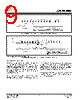
7 / 17 page  GPR26L080A © Generalplus Technology Inc. Proprietary & Confidential 7 AUG. 13, 2009 Version: 1.3 8. OPERATING FEATURES 8.1. Active Power, Stand-by Power When Chip Select (SB) is Low, the device is enabled with current consumption of ICC2 in the Active Power mode (regardless of whether or not the clock is toggled). When Chip Select (SB) is High, the device is disabled, but it remains in the Active Power mode until all internal cycles are completed. After that, the device enters standby mode, dropping the current to ICC1. 8.2. Protection Modes The environments where non-volatile memory devices are used can be very noisy. No SPI device can operate correctly in the presence of excessive noise. To help combat this, the GPR26L080A boasts the following data protection mechanisms: - Power-On Reset and an internal timer (tPUW) can provide protection against inadvertent changes while the power supply is outside the operating specification. 8.3. Hold Condition The Hold (HOLDB) signal is used to pause any serial communications with the device without resetting the clocking sequence. To enter the Hold condition, the device must be selected, with Chip Select (SB) Low. The Hold condition starts on the falling edge of the Hold (HOLD) signal, provided that this coincides with Serial Clock (C) being Low (as shown in Figure 3). The Hold condition ends on the rising edge of the Hold (HOLDB) signal, provided that this coincides with Serial Clock (C) being Low. If the falling edge does not coincide with Serial Clock (C) being Low, the Hold condition starts after Serial Clock (C) next goes Low. Similarly, if the rising edge does not coincide with Serial Clock (C) being Low, the Hold condition ends after Serial Clock (C) next goes Low. (This is shown in Figure 2). During the Hold condition, the Serial Data Output (Q) is high impedance, and Serial Data Input (D) and Serial Clock (C) are Don't Care. Normally, the device is kept selected, with Chip Select (SB) driven Low, for the whole duration of the Hold condition. This is to ensure that the state of the internal logic remains unchanged from the moment of entering the Hold condition. If Chip Select (SB) goes High while the device is in the Hold condition, this has the effect of resetting the internal logic of the device. To restart communication with the device, it is necessary to drive Hold (HOLDB) High, and then to drive Chip Select (SB) Low. This prevents the device from going back to the Hold condition. HOLDB HOLDB Figure3. Hold Condition Activation (for data output only) |
|
|
リンク URL |
| ALLDATASHEETはお客様のビジネスに役立ちますか? [ DONATE ] |
Alldatasheetは | 広告 | お問い合わせ | プライバシーポリシー | データシートへのリンク | リンク交換 | メーカーリスト All Rights Reserved©Alldatasheet.com |
| Russian : Alldatasheetru.com | Korean : Alldatasheet.co.kr | Spanish : Alldatasheet.es | French : Alldatasheet.fr | Italian : Alldatasheetit.com Portuguese : Alldatasheetpt.com | Polish : Alldatasheet.pl | Vietnamese : Alldatasheet.vn Indian : Alldatasheet.in | Mexican : Alldatasheet.com.mx | British : Alldatasheet.co.uk | New Zealand : Alldatasheet.co.nz |
|
Family Site : ic2ic.com |
icmetro.com |
 Japanese ▼
 English
 Chinese
 German
 Japanese
 Russian
 Korean
 Spanish
 French
 Italian
 Portuguese
 Polish
 Vietnamese
 Indian
 Mexican
 British
 New Zealand