|
データシートサーチシステム |
|
|
データシートサーチシステム |
|
ADRF5250BCPZ-R7 データシート(PDF) 6 Page - Analog Devices |
|
|
|||||||||||||||||||||||||||||
ADRF5250BCPZ-R7 データシート(HTML) 6 Page - Analog Devices |
|
|
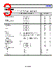
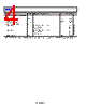
6 / 15 page  ADRF5250 Data Sheet Rev. 0 | Page 6 of 15 PIN CONFIGURATION AND FUNCTION DESCRIPTIONS 2 1 3 4 5 6 18 17 16 15 14 13 GND RF4 GND GND RF5 GND GND RF1 GND VDD V1 V2 ADRF5250 TOP VIEW (Not to Scale) NOTES 1. EXPOSED PAD. THE EXPOSED PAD MUST BE CONNECTED TO THE RF/DC GROUND OF THE PCB. Figure 2. Pin Configuration Table 3. Pin Function Descriptions Pin No. Mnemonic Description 1, 3, 4, 6, 7, 9, 10, 12, 13, 15, 21, 23, 24 GND Ground. These pins must be connected to the RF/dc ground of the printed circuit board (PCB). 2 RF5 RF Throw Port 5. This pin is dc coupled and no dc blocking capacitor is necessary when the RF line potential is within 0 V dc. 5 RF4 RF Throw Port 4. This pin is dc coupled and no dc blocking capacitor is necessary when the RF line potential is within 0 V dc. 8 RF3 RF Throw Port 3. This pin is dc coupled and no dc blocking capacitor is necessary when the RF line potential is within 0 V dc. 11 RF2 RF Throw Port 2. This pin is dc coupled and no dc blocking capacitor is necessary when the RF line potential is within 0 V dc. 14 RF1 RF Throw Port 1. This pin is dc coupled and no dc blocking capacitor is necessary when the RF line potential is within 0 V dc. 16 VDD Positive Supply Voltage. 17 V1 Digital Input Voltage Applied to the Least Significant Bit (LSB) of Digital Interface for Controlling RF Path State. See Table 5. 18 V2 Digital Input Voltage Applied to the Second Bit of Digital Interface for Controlling RF Path State. See Table 5. 19 V3 Digital Input Voltage Applied to the Most Significant Bit (MSB) of Digital Interface for Controlling RF Path State. See Table 5. 20 VSS Optional Negative Supply Voltage. This pin can be connected to ground to operate with the internal negative voltage generator. The internal negative voltage generator is disabled when this pin is connected to an external 3.3 V supply. 22 RFC RF Common Port. This pin is dc-coupled and no dc blocking capacitor is necessary when the RF line potential is within 0 V dc. EPAD Exposed Pad. The exposed pad must be connected to the RF/dc ground of the PCB. |
|
|
リンク URL |
| ALLDATASHEETはお客様のビジネスに役立ちますか? [ DONATE ] |
Alldatasheetは | 広告 | お問い合わせ | プライバシーポリシー | データシートへのリンク | リンク交換 | メーカーリスト All Rights Reserved©Alldatasheet.com |
| Russian : Alldatasheetru.com | Korean : Alldatasheet.co.kr | Spanish : Alldatasheet.es | French : Alldatasheet.fr | Italian : Alldatasheetit.com Portuguese : Alldatasheetpt.com | Polish : Alldatasheet.pl | Vietnamese : Alldatasheet.vn Indian : Alldatasheet.in | Mexican : Alldatasheet.com.mx | British : Alldatasheet.co.uk | New Zealand : Alldatasheet.co.nz |
|
Family Site : ic2ic.com |
icmetro.com |
 Japanese ▼
 English
 Chinese
 German
 Japanese
 Russian
 Korean
 Spanish
 French
 Italian
 Portuguese
 Polish
 Vietnamese
 Indian
 Mexican
 British
 New Zealand