|
データシートサーチシステム |
|
|
データシートサーチシステム |
|
CSL0902ET1 データシート(PDF) 9 Page - Rohm |
|
|
|||||||||||||||||||||||||||||
CSL0902ET1 データシート(HTML) 9 Page - Rohm |
|
|
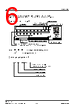
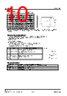
9 / 17 page  [CSL0902ET1] [Data Sheet] 4.Mounting 4-1. Soldering 4-2. Automatic Mounting 4-2-1.Suction nozzle 4-2-2.Mini Package (Smaller than 1608 size) 4-3. Mounting Location 4-4. Mechanical Stress after Mounting 4-5. Soldering Pattern for Recommendation (Unit:mm) ・No resin hardening agent such as filler is used in the sealing resin of the product. Therefore, resin expansion and moisture absorption at humidity will cause heat stress during soldering process and finally has bad influence on the product’s reliability. ・The product is not guaranteed for flow soldering. ・Do not expose the product in the environment of high temperature (over 100℃) or rapid temperature shift (within 3℃/sec. of temperature gradient) during the flow soldering of surrounding parts. In case of carrying out flow soldering of surrounding parts without recommended conditions, please contact us for inquiries. ・Please set appropriate reflow temperature based on our product usage conditions and specification. ・The max for reflowing is 2 times, please finish the second reflow soldering and flow soldering with other parts within the usage limitation after open the moistureproof package. ・Compare with N2 reflow, during air reflow, because of the heat and surrounding conditions, it may cause the discoloration of the resin. ・For our product that has no solder resist, because of its solder amount and soldering conditions, one of its specific characteristics is that solder will penetrate into LED. Thus, there's high possibility that will influence its reliability. Therefore, please be informed, concerning it before using it. Excessive load may cause damage inside the LED product, so select an optimal suction nozzle according to the material and shape of the LED product. Vibration may result in low mounting rate since it will cause the static electricity of product and adhere to top cover tape. We recommend to ・set magnet on parts feeder cassette of the mounter to control the product stabilization ・set ionizer to prevent electrostatic charge The stress like bending stress of circuit board dividing after mounting, may cause LED package crack or damage of LED internal junction, therefore, please concern the mounting direction and position to avoid bending or screwing with great stress of the circuit board. Stress strength according to the mounting position: A>B>C>D The mechanical stress may damage the LED after circuit mounting, so please pay attention to the touch on product. We recommend the soldering pattern that shows on the right. It will be different according to mounting situation of circuit board, therefore, please concern before designing. ※The product has adopted the electrode structure that it should solder with back electrode of the product. Thus, please be informed that the shape of electrode pin of solder fillet formation is not guaranteed. The through hole on electrode surface is for conduction of front and rear electrodes but not for formation of solder fillet. 9/15 2022.7 - Rev.002 www.rohm.com ©2022 ROHM Co., Ltd. All rights reserved |
|
|
リンク URL |
| ALLDATASHEETはお客様のビジネスに役立ちますか? [ DONATE ] |
Alldatasheetは | 広告 | お問い合わせ | プライバシーポリシー | データシートへのリンク | リンク交換 | メーカーリスト All Rights Reserved©Alldatasheet.com |
| Russian : Alldatasheetru.com | Korean : Alldatasheet.co.kr | Spanish : Alldatasheet.es | French : Alldatasheet.fr | Italian : Alldatasheetit.com Portuguese : Alldatasheetpt.com | Polish : Alldatasheet.pl | Vietnamese : Alldatasheet.vn Indian : Alldatasheet.in | Mexican : Alldatasheet.com.mx | British : Alldatasheet.co.uk | New Zealand : Alldatasheet.co.nz |
|
Family Site : ic2ic.com |
icmetro.com |
 Japanese ▼
 English
 Chinese
 German
 Japanese
 Russian
 Korean
 Spanish
 French
 Italian
 Portuguese
 Polish
 Vietnamese
 Indian
 Mexican
 British
 New Zealand