|
データシートサーチシステム |
|
|
データシートサーチシステム |
|
AD5663BCPZ-R2 データシート(PDF) 17 Page - Analog Devices |
|
|
|||||||||||||||||||||||||||||
AD5663BCPZ-R2 データシート(HTML) 17 Page - Analog Devices |
|
|
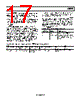
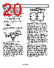
17 / 24 page  AD5663 Rev. 0 | Page 17 of 24 Synchronous LDAC: The DAC registers are updated after new data is read in on the falling edge of the 24th SCLK pulse. LDAC can be permanently low or pulsed, as shown in Figure 2. Asynchronous LDAC: The outputs are not updated at the same time that the input registers are written to. When LDAC goes low, the DAC registers are updated with the contents of the input register. The LDAC register gives the user full flexibility and control over the hardware LDAC pin. This register allows the user to select which combination of channels to simultaneously update when the hardware LDAC pin is executed. Setting the LDAC bit register to 0 for a DAC channel means that the update of this channel is controlled by the LDAC pin. If this bit is set to 1, this channel synchronously updates; that is, the DAC register is updated after new data is read in, regardless of the state of the LDAC pin. It effectively sees the LDAC pin as being pulled low. See Table 13 for the LDAC register mode of operation. This flexibility is useful in applications where the user wants to simultaneously update select channels while the rest of the channels are synchronously updating Writing to the DAC using Command 110 loads the 2-bit LDAC register [DB1:DB0]. The default for each channel is 0; that is, the LDAC pin works normally. Setting the bits to 1 means the DAC register is updated regardless of the state of the LDAC pin. See Table 14 for contents of the input shift register during the LDAC register setup command. Table 13. LDAC Register Mode of Operation LDAC Bits (DB1 to DB0) LDAC Pin LDAC Operation 0 1/0 Determined by LDAC pin 1 x = don’t care The DAC registers are updated after new data is read in on the falling edge of the 24th SCLK pulse Table 14. 24-Bit Input Shift Register Contents for LDAC Register Setup Command MSB LSB DB23 to DB22 DB21 DB20 DB19 DB18 DB17 DB16 DB15 to DB2 DB1 DB0 x 1 1 0 x x x x DAC B DAC A Don’t care Command bits (C2 to C0) Address bits (A3 to A0); Don’t care Don’t care Set DAC to 0 or 1 for required mode of operation |
|
|
リンク URL |
| ALLDATASHEETはお客様のビジネスに役立ちますか? [ DONATE ] |
Alldatasheetは | 広告 | お問い合わせ | プライバシーポリシー | データシートへのリンク | リンク交換 | メーカーリスト All Rights Reserved©Alldatasheet.com |
| Russian : Alldatasheetru.com | Korean : Alldatasheet.co.kr | Spanish : Alldatasheet.es | French : Alldatasheet.fr | Italian : Alldatasheetit.com Portuguese : Alldatasheetpt.com | Polish : Alldatasheet.pl | Vietnamese : Alldatasheet.vn Indian : Alldatasheet.in | Mexican : Alldatasheet.com.mx | British : Alldatasheet.co.uk | New Zealand : Alldatasheet.co.nz |
|
Family Site : ic2ic.com |
icmetro.com |
 Japanese ▼
 English
 Chinese
 German
 Japanese
 Russian
 Korean
 Spanish
 French
 Italian
 Portuguese
 Polish
 Vietnamese
 Indian
 Mexican
 British
 New Zealand