|
データシートサーチシステム |
|
|
データシートサーチシステム |
|
AD8318ACPZ-R2 データシート(PDF) 15 Page - Analog Devices |
|
|
|||||||||||||||||||||||||||||
AD8318ACPZ-R2 データシート(HTML) 15 Page - Analog Devices |
|
|
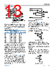
15 / 24 page  Data Sheet AD8318 USING THE AD8318 analog.com Rev. E | 15 of 24 When X = 1, the typical output voltage swing is 0.5 V to 2.1 V. The output voltage swing is modeled using Equation 5 to Equation 7 and restricted by Equation 8: VOUT(MIN) < VOUT < VOUT(MAX) (8) When X = 4 and VPOS = 5 V, (X × VOFFSET) < VOUT < (VPOS − 400 mV) (4 × 0.5 V) < VOUT < (2.1 V × 4) 2 V < VOUT < 4.6 V For X = 4, slope = −100 mV/dB; VOUT can swing 2.6 V, and the usable dynamic range is reduced to 26 dB from 0 dBm to –26 dBm. The slope is very stable vs. process and temperature variation. When base-10 logarithms are used, VSLOPE/DECADE represents the output voltage per decade of input power. One decade is equal to 20 dB; VSLOPE/DEC/20 = VSLOPE/dB represents the output voltage slope in V/dB. As noted in Equation 3, the VOUT voltage has a negative slope. This is the correct slope polarity to control the gain of many power amplifiers and other VGAs in a negative feedback configuration. Because both the slope and intercept vary slightly with frequency, refer to Table 1 for application-specific values for the slope and intercept. Although demodulating log amps respond to input signal voltage, not input signal power, it is customary to discuss the amplitude of high frequency signals in terms of power. In this case, the characteristic impedance of the system, Z0, must be known to convert voltages to corresponding power levels. Beginning with the definitions of dBm and dBV, P (dBm) = 10 × log10(Vrms2/(Z0 × 1 mW)) (9) V (dBV) = 20 × log10(Vrms/1 Vrms) (10) When Equation 9 is expanded P (dBm) = 20 × log10(Vrms) − 10 × log10(Z0 × 1 mW) (11) and given Equation 10, Equation 11 can be rewritten as P (dBm) = V (dBV) − 10 × log10(Z0 × 1 mW) (12) For example, PINTERCEPT for a sinusoidal input signal, expressed in terms of dBm (decibels referred to 1 mW), in a 50 Ω system is PINTERCEPT (dBm) = VINTERCEPT (dBV) − 10 × log10(Z0 × 1 mW) = (13) 7 dBV − 10 × log10(50 × 10−3) = 20 dBm For further information on the intercept variation dependence upon waveform, refer to the AD8313 and AD8307 data sheets. DEVICE CALIBRATION AND ERROR CALCULATION The measured transfer function of the AD8318 at 2.2 GHz is shown in Figure 32. The figure shows plots of both output voltage vs. input power and calculated log conformance error vs. input power. As the input power varies from −65 dBm to 0 dBm, the output voltage varies from 2 V to about 0.5 V. Figure 32. Transfer Function at 2.2 GHz Because the slope and intercept vary from device to device, board- level calibration is performed to achieve high accuracy. The equation can be rewritten for output voltage, from the Measure- ment Mode section, using an intercept expressed in dBm. VOUT = Slope × (PIN – Intercept) (14) In general, the calibration is performed by applying two known signal levels to the AD8318 input and measuring the corresponding output voltages. The calibration points are generally chosen to be within the linear-in-dB operating range of the device (see Figure 32). Calculation of the slope and intercept is done by: Slope = (VOUT1 − VOUT2)/(PIN1 − PIN2) (15) Intercept = PIN1 − VOUT1/Slope (16) Once the slope and intercept are calculated, an equation can be written to allow calculation of an (unknown) input power based on the output voltage of the detector. PIN(unknown) = VOUT (measured)/Slope + Intercept (17) Using the equation for the ideal output voltage (see Equation 13) as a reference, the log conformance error of the measured data can be calculated as Error (dB) = (VOUT(MEASURED) − VOUT(IDEAL))/Slope (18) Figure 32 includes a plot of the error at 25°C, the temperature at which the log amp is calibrated. Note that the error is not zero. This is because the log amp does not perfectly follow the ideal VOUT |
|
|
リンク URL |
| ALLDATASHEETはお客様のビジネスに役立ちますか? [ DONATE ] |
Alldatasheetは | 広告 | お問い合わせ | プライバシーポリシー | データシートへのリンク | リンク交換 | メーカーリスト All Rights Reserved©Alldatasheet.com |
| Russian : Alldatasheetru.com | Korean : Alldatasheet.co.kr | Spanish : Alldatasheet.es | French : Alldatasheet.fr | Italian : Alldatasheetit.com Portuguese : Alldatasheetpt.com | Polish : Alldatasheet.pl | Vietnamese : Alldatasheet.vn Indian : Alldatasheet.in | Mexican : Alldatasheet.com.mx | British : Alldatasheet.co.uk | New Zealand : Alldatasheet.co.nz |
|
Family Site : ic2ic.com |
icmetro.com |
 Japanese ▼
 English
 Chinese
 German
 Japanese
 Russian
 Korean
 Spanish
 French
 Italian
 Portuguese
 Polish
 Vietnamese
 Indian
 Mexican
 British
 New Zealand