|
データシートサーチシステム |
|
|
データシートサーチシステム |
|
ADCLK944BCPZ-R7 データシート(PDF) 5 Page - Analog Devices |
|
|
|||||||||||||||||||||||||||||
ADCLK944BCPZ-R7 データシート(HTML) 5 Page - Analog Devices |
|
|
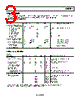
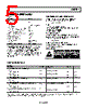
5 / 12 page  ADCLK944 Rev. 0 | Page 5 of 12 ABSOLUTE MAXIMUM RATINGS Table 4. Parameter Rating Supply Voltage VCC − VEE 6.0 V Input Voltage CLK, CLK VEE − 0.5 V to VCC + 0.5 V CLK to CLK ±1.8 V Input Termination, VT to CLK, CLK ±2 V Input Current, CLK, CLK to VT Pin (CML, LVPECL Termination) ±40 mA Maximum Voltage on Output Pins VCC + 0.5 V Maximum Output Current 35 mA Voltage Reference (VREF) VCC to VEE Operating Temperature Ambient Range −40°C to +85°C Junction 150°C Storage Temperature Range −65°C to +150°C Stresses above those listed under Absolute Maximum Ratings may cause permanent damage to the device. This is a stress rating only; functional operation of the device at these or any other conditions above those indicated in the operational section of this specification is not implied. Exposure to absolute maximum rating conditions for extended periods may affect device reliability. DETERMINING JUNCTION TEMPERATURE To determine the junction temperature on the application printed circuit board (PCB), use the following equation: TJ = TCASE + (ΨJT × PD) where: TJ is the junction temperature (°C). TCASE is the case temperature (°C) measured by the customer at the top center of the package. ΨJT is as indicated in Table 5. PD is the power dissipation. Values of θJA are provided for package comparison and PCB design considerations. θJA can be used for a first-order approx- imation of TJ using the following equation: TJ = TA + (θJA × PD) where TA is the ambient temperature (°C). Values of θJB are provided in Table 5 for package comparison and PCB design considerations. ESD CAUTION THERMAL PERFORMANCE Table 5. Parameter Symbol Description Value1 Unit Junction-to-Ambient Thermal Resistance Still Air θJA Per JEDEC JESD51-2 0.0 m/sec Airflow 78 °C/W Moving Air θJMA Per JEDEC JESD51-6 1.0 m/sec Airflow 68 °C/W 2.5 m/sec Airflow 61 °C/W Junction-to-Board Thermal Resistance θJB Per JEDEC JESD51-8 Moving Air 1.0 m/sec Airflow 49 °C/W Junction-to-Case Thermal Resistance (Die-to-Heat Sink) θJC Per MIL-STD-883, Method 1012.1 Still Air 0.0 m/sec Airflow 1.5 °C/W Junction-to-Top-of-Package Characterization Parameter ΨJT Still Air Per JEDEC JESD51-2 0.0 m/sec Airflow 2.0 °C/W 1 Results are from simulations. The PCB is a JEDEC multilayer type. Thermal performance for actual applications requires careful inspection of the conditions in the application to determine whether they are similar to those assumed in these calculations. |
|
|
リンク URL |
| ALLDATASHEETはお客様のビジネスに役立ちますか? [ DONATE ] |
Alldatasheetは | 広告 | お問い合わせ | プライバシーポリシー | データシートへのリンク | リンク交換 | メーカーリスト All Rights Reserved©Alldatasheet.com |
| Russian : Alldatasheetru.com | Korean : Alldatasheet.co.kr | Spanish : Alldatasheet.es | French : Alldatasheet.fr | Italian : Alldatasheetit.com Portuguese : Alldatasheetpt.com | Polish : Alldatasheet.pl | Vietnamese : Alldatasheet.vn Indian : Alldatasheet.in | Mexican : Alldatasheet.com.mx | British : Alldatasheet.co.uk | New Zealand : Alldatasheet.co.nz |
|
Family Site : ic2ic.com |
icmetro.com |
 Japanese ▼
 English
 Chinese
 German
 Japanese
 Russian
 Korean
 Spanish
 French
 Italian
 Portuguese
 Polish
 Vietnamese
 Indian
 Mexican
 British
 New Zealand