|
データシートサーチシステム |
|
|
データシートサーチシステム |
|
ADA4830-2BCPZ-R2 データシート(PDF) 17 Page - Analog Devices |
|
|
|||||||||||||||||||||||||||||
ADA4830-2BCPZ-R2 データシート(HTML) 17 Page - Analog Devices |
|
|
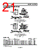
17 / 22 page  Data Sheet ADA4830-1/ADA4830-2 Rev. C | Page 17 of 22 DRIVING CAPACITIVE LOADS The ADA4830-1 and ADA4830-2 are capable of driving large capacitive loads while maintaining its rated performance. Several performance curves vs. capacitive load are shown in Figure 12 and Figure 25. Capacitive loads interact with an op amp’s output impedance to create an extra delay in the feedback path. This reduces circuit stability and can cause unwanted ringing and oscillation. The capacitive load drive of the ADA4830-1and ADA4830-2 can be increased by adding a low valued resistor, RS, in series with the capacitive load. Figure 35 shows the test circuit. ADA4830-1 + – CL = 47pF RS = 49.9Ω RL = 1kΩ Figure 35. RS Test Circuit Introducing a series resistor tends to isolate the capacitive load from the feedback loop, thereby diminishing its influence. One drawback to this approach is a slight loss of signal amplitude. Figure 36 shows the effects of a series resistor on the capacitive drive. For very large capacitive loads, the frequency response of the amplifier is dominated by the roll-off of the series resistor and capacitive load. 1.0 1.5 2.0 2.5 3.0 3.5 4.0 0 50 100 150 200 250 TIME (ns) +VS = 5V RL = 1kΩ CL = 47pF NO RS RS = 49.9Ω Figure 36. Pulse Response With and Without Series Resistor Another method of reducing the resonant peaking caused by driving large capacitive loads at the output of the ADA4830-1 and ADA4830-2 is with the use of a R-C shunt circuit or a snubber circuit. This method acts to resistively load the amplifier output, thus reducing frequency response peaking. One drawback to this approach is a slight loss of signal bandwidth. Figure 37 shows a simple circuit representation of the implementation of the R-C snubber circuit with RSNT and CSNT. Figure 38 shows the effects of a R-C snubber circuit driving 47 pF, where RSNT = 73.2 Ω and CSNT = 0.1 µF. ADA4830-1 + – CL = 47pF CSNT = 0.1uF RL = 1kΩ RSNT = 73.2Ω Figure 37. R-C Test Circuit 1.0 1.5 2.0 2.5 3.0 3.5 4.0 0 50 100 150 200 250 TIME (ns) +VS = 5V RL = 1kΩ CL = 47pF NO SNUBBER CIRCUIT RSNT = 73.2Ω CSNT = 0.1µF Figure 38. Pulse Response With and Without R-C Snubber Circuit |
|
|
リンク URL |
| ALLDATASHEETはお客様のビジネスに役立ちますか? [ DONATE ] |
Alldatasheetは | 広告 | お問い合わせ | プライバシーポリシー | データシートへのリンク | リンク交換 | メーカーリスト All Rights Reserved©Alldatasheet.com |
| Russian : Alldatasheetru.com | Korean : Alldatasheet.co.kr | Spanish : Alldatasheet.es | French : Alldatasheet.fr | Italian : Alldatasheetit.com Portuguese : Alldatasheetpt.com | Polish : Alldatasheet.pl | Vietnamese : Alldatasheet.vn Indian : Alldatasheet.in | Mexican : Alldatasheet.com.mx | British : Alldatasheet.co.uk | New Zealand : Alldatasheet.co.nz |
|
Family Site : ic2ic.com |
icmetro.com |
 Japanese ▼
 English
 Chinese
 German
 Japanese
 Russian
 Korean
 Spanish
 French
 Italian
 Portuguese
 Polish
 Vietnamese
 Indian
 Mexican
 British
 New Zealand