|
データシートサーチシステム |
|
|
データシートサーチシステム |
|
AD587JR データシート(PDF) 9 Page - Analog Devices |
|
|
|||||||||||||||||||||||||||||
AD587JR データシート(HTML) 9 Page - Analog Devices |
|
|
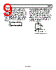
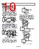
9 / 12 page  AD587 Rev. H | Page 9 of 12 Each AD587J and AD587K grade unit is tested at 0°C, 25°C, and 70°C. Each AD587U grade unit is tested at −55°C, +25°C, and +125°C. This approach ensures that the variations of the output voltage that occur as the temperature changes within the specified range are contained within a box whose diagonal has a slope equal to the maximum specified drift. The position of the box on the vertical scale changes from device to device as initial error and the shape of the curve vary. The maximum height of the box for the appropriate temperature range and device grade is shown in Figure 16. Duplication of these results requires a combination of high accuracy and stable temperature control in a test system. DEVICE GRADE AD587J AD587K AD587U 14.00 7.00 9.00 0 TO +70°C –55°C TO +125°C MAXIMUM OUTPUT CHANGE – mV Figure 16. Maximum Output Change in Millivolts NEGATIVE REFERENCE VOLTAGE FROM AN AD587 The AD587 can be used as shown in Figure 17 to provide a precision −10.000 V output. The +VIN pin is tied to at least a +3.5 V supply, the output pin is grounded, and the AD587 ground pin is connected through a resistor (RS) to a −15 V supply. The −10 V output is taken from the ground pin (Pin 4) instead of VOUT. It is essential to arrange the output load and the supply resistor (RS) so that the net current through the AD587 is between 2.5 mA and 10.0 mA (RS should be kept below 1 kΩ). The temperature characteristics and long-term stability of the device is essentially the same as that of a unit used in the standard 10 V output configuration. 2 6 4 GND AD587 3.5V→26V 1nF RS –15V –10V +VIN VOUT ←IL 2.5mA < 5V RS – IL < 10mA Figure 17. AD587 as a Negative 10 V Reference |
|
|
リンク URL |
| ALLDATASHEETはお客様のビジネスに役立ちますか? [ DONATE ] |
Alldatasheetは | 広告 | お問い合わせ | プライバシーポリシー | データシートへのリンク | リンク交換 | メーカーリスト All Rights Reserved©Alldatasheet.com |
| Russian : Alldatasheetru.com | Korean : Alldatasheet.co.kr | Spanish : Alldatasheet.es | French : Alldatasheet.fr | Italian : Alldatasheetit.com Portuguese : Alldatasheetpt.com | Polish : Alldatasheet.pl | Vietnamese : Alldatasheet.vn Indian : Alldatasheet.in | Mexican : Alldatasheet.com.mx | British : Alldatasheet.co.uk | New Zealand : Alldatasheet.co.nz |
|
Family Site : ic2ic.com |
icmetro.com |
 Japanese ▼
 English
 Chinese
 German
 Japanese
 Russian
 Korean
 Spanish
 French
 Italian
 Portuguese
 Polish
 Vietnamese
 Indian
 Mexican
 British
 New Zealand