|
データシートサーチシステム |
|
|
データシートサーチシステム |
|
24AA128 データシート(PDF) 10 Page - Microchip Technology |
|
|
|||||||||||||||||||||||||||||
24AA128 データシート(HTML) 10 Page - Microchip Technology |
|
|
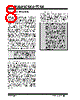
10 / 38 page  24AA128/24LC128/24FC128 DS21191S-page 10 2010 Microchip Technology Inc. 8.0 READ OPERATION Read operations are initiated in much the same way as write operations with the exception that the R/W bit of the control byte is set to ‘ 1’. There are three basic types of read operations: current address read, random read and sequential read. 8.1 Current Address Read The 24XX128 contains an address counter that main- tains the address of the last word accessed, internally incremented by ‘ 1’. Therefore, if the previous read access was to address ‘ n’ (n is any legal address), the next current address read operation would access data from address n + 1. Upon receipt of the control byte with R/W bit set to ‘ 1’, the 24XX128 issues an acknowledge and transmits the 8-bit data word. The master will not acknowledge the transfer, but does generate a Stop condition and the 24XX128 discontinues transmission (Figure 8-1). FIGURE 8-1: CURRENT ADDRESS READ 8.2 Random Read Random read operations allow the master to access any memory location in a random manner. To perform this type of read operation, the word address must first be set. This is done by sending the word address to the 24XX128 as part of a write operation (R/W bit set to ‘ 0’). Once the word address is sent, the master gener- ates a Start condition following the acknowledge. This terminates the write operation, but not before the inter- nal Address Pointer is set. The master then issues the control byte again, but with the R/W bit set to a ‘ 1’. The 24XX128 will then issue an acknowledge and transmit the 8-bit data word. The master will not acknowledge the transfer but does generate a Stop condition, which causes the 24XX128 to discontinue transmission (Figure 8-2). After a random Read command, the internal address counter will point to the address location following the one that was just read. 8.3 Sequential Read Sequential reads are initiated in the same way as a random read except that after the 24XX128 transmits the first data byte, the master issues an acknowledge as opposed to the Stop condition used in a random read. This acknowledge directs the 24XX128 to transmit the next sequentially addressed 8-bit word (Figure 8-3). Following the final byte transmitted to the master, the master will NOT generate an acknowledge but will generate a Stop condition. To provide sequential reads, the 24XX128 contains an internal Address Pointer which is incremented by one at the completion of each operation. This Address Pointer allows the entire memory contents to be serially read during one operation. The internal Address Pointer will automatically roll over from address 3FFF to address 0000 if the master acknowledges the byte received from the array address 3FFF. FIGURE 8-2: RANDOM READ FIGURE 8-3: SEQUENTIAL READ Bus Activity Master SDA Line Bus Activity P S S T O P Control Byte S T A R T Data A C K N O A C K 11 00 AA A 1 Byte 21 0 xx Bus Activity Master SDA Line Bus Activity A C K N O A C K A C K A C K A C K S T O P S T A R T Control Byte Address High Byte Address Low Byte Control Byte Data Byte S T A R T x = “don’t care” bit S 10 10 AA A 0 21 0 S 1 010 AAA 1 210 P Bus Activity Master SDA Line Bus Activity Control Byte Data (n) Data (n + 1) Data (n + 2) Data (n + x) N O A C K A C K A C K A C K A C K S T O P P |
|
リンク URL |
| ALLDATASHEETはお客様のビジネスに役立ちますか? [ DONATE ] |
Alldatasheetは | 広告 | お問い合わせ | プライバシーポリシー | データシートへのリンク | リンク交換 | メーカーリスト All Rights Reserved©Alldatasheet.com |
| Russian : Alldatasheetru.com | Korean : Alldatasheet.co.kr | Spanish : Alldatasheet.es | French : Alldatasheet.fr | Italian : Alldatasheetit.com Portuguese : Alldatasheetpt.com | Polish : Alldatasheet.pl | Vietnamese : Alldatasheet.vn Indian : Alldatasheet.in | Mexican : Alldatasheet.com.mx | British : Alldatasheet.co.uk | New Zealand : Alldatasheet.co.nz |
|
Family Site : ic2ic.com |
icmetro.com |
 Japanese ▼
 English
 Chinese
 German
 Japanese
 Russian
 Korean
 Spanish
 French
 Italian
 Portuguese
 Polish
 Vietnamese
 Indian
 Mexican
 British
 New Zealand