|
データシートサーチシステム |
|
|
データシートサーチシステム |
|
TAS2553 データシート(PDF) 25 Page - Texas Instruments |
|
|
|||||||||||||||||||||||||||||
TAS2553 データシート(HTML) 25 Page - Texas Instruments |
|
|
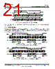
25 / 58 page  LD(n) LD (n+1) BIT CLOCK DATA N - 1 N - 2 N - 3 2 1 0 3 N - 1 N - 2 N - 3 0 3 2 1 N - 1 N - 2 N - 3 3 RD(n) WORD CLOCK LEFT CHANNEL RIGHT CHANNEL LD(n) LD(n+1) BIT CLOCK DATA - 1 - 2 - 3 2 1 0 3 - 1 - 2 - 3 0 3 2 1 - 1 - 2 N N N N N N N N N - 3 RD(n) WORD CLOCK LEFT CHANNEL RIGHT CHANNEL LD(n)=n'thsampleofleftchanneldata RD(n)=n'thsampleofrightchanneldata LD(n) LD (n+1) BIT CLOCK DATA - 1 - 2 - 3 2 1 0 3 - 1 - 2 - 3 0 3 2 1 - 1 - 2 N N N N N N N N N - 3 3 RD(n) WORD CLOCK LEFT CHANNEL RIGHT CHANNEL LD(n)=n'thsampleofleftchanneldata RD(n)=n'thsampleofrightchanneldata TAS2553 www.ti.com SLAS978B – SEPTEMBER 2013 – REVISED FEBRUARY 2014 7.4.1.5 DSP Mode Set Register 0x03, D(7:6) = 01 and Register 0x05, D(3:2) = 01 to place the TAS2553 audio interface into DSP mode. In DSP mode, the rising edge of the word clock starts the data transfer with the left channel data first and immediately followed by the right channel data. Each data bit is valid on the falling edge of the bit clock. Figure 39. Timing Diagram for DSP Mode Figure 40. Timing Diagram for DSP Mode with Offset=1 Figure 41. Timing Diagram for DSP Mode with Offset=0 and Inverted Bit Clock For DSP mode, the number of bit-clocks per frame should be greater than twice the programmed word-length of the data. Also the programmed offset value should be less than the number of bit-clocks per frame by at least the programmed word-length of the data. Copyright © 2013–2014, Texas Instruments Incorporated Submit Documentation Feedback 25 Product Folder Links: TAS2553 |
|
リンク URL |
| ALLDATASHEETはお客様のビジネスに役立ちますか? [ DONATE ] |
Alldatasheetは | 広告 | お問い合わせ | プライバシーポリシー | データシートへのリンク | リンク交換 | メーカーリスト All Rights Reserved©Alldatasheet.com |
| Russian : Alldatasheetru.com | Korean : Alldatasheet.co.kr | Spanish : Alldatasheet.es | French : Alldatasheet.fr | Italian : Alldatasheetit.com Portuguese : Alldatasheetpt.com | Polish : Alldatasheet.pl | Vietnamese : Alldatasheet.vn Indian : Alldatasheet.in | Mexican : Alldatasheet.com.mx | British : Alldatasheet.co.uk | New Zealand : Alldatasheet.co.nz |
|
Family Site : ic2ic.com |
icmetro.com |
 Japanese ▼
 English
 Chinese
 German
 Japanese
 Russian
 Korean
 Spanish
 French
 Italian
 Portuguese
 Polish
 Vietnamese
 Indian
 Mexican
 British
 New Zealand