|
データシートサーチシステム |
|
|
データシートサーチシステム |
|
AD7922AUJ-R2 データシート(PDF) 15 Page - Analog Devices |
|
|
|||||||||||||||||||||||||||||
AD7922AUJ-R2 データシート(HTML) 15 Page - Analog Devices |
|
|
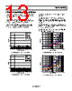
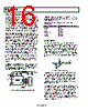
15 / 32 page  AD7912/AD7922 Rev. 0 | Page 15 of 32 CIRCUIT INFORMATION The AD7912/AD7922 are fast, 2-channel, 10-/12-bit, single supply, analog-to-digital converters (ADCs), respectively. The parts can be operated from a 2.35 V to 5.25 V supply. When operated from either a 5 V supply or a 3 V supply, the AD7912/AD7922 are capable of throughput rates of 1 MSPS when provided with an 18 MHz clock. The AD7912/AD7922 provide the user with an on-chip track- and-hold, an ADC, and a serial interface, all housed in a tiny 8-lead TSOT package or 8-lead MSOP package, which offer the user considerable space-saving advantages over alternative solutions. The serial clock input accesses data from the parts, controls the transfer of data written to the ADC, and provides the clock source for the successive approximation ADC. The analog input range is 0 to VDD. An external reference is not required for the ADC, and neither is there a reference on-chip. The reference for the AD7912/AD7922 is derived from the power supply and, therefore, gives the widest dynamic input range. The AD7912/AD7922 feature a power-down option that allows power saving between conversions. The power-down feature is implemented across the standard serial interface as described in the Modes of Operation section. The AD7912/AD7922 can also be used in daisy-chain mode when several AD7912/AD7922 are connected in a daisy chain. This mode of operation is selected by controlling the logic state of the CS signal. The fourth MSB on the DOUT pin indicates if the ADC is in normal mode or daisy-chain mode. CONVERTER OPERATION The AD7912/AD7922 are 10-/12-bit successive approximation ADCs based around a charge redistribution DAC. Figure 19 and Figure 20 show simplified schematics of the ADC. Figure 19 shows the ADC during its acquisition phase. SW2 is closed and SW1 is in Position A, the comparator is held in a balanced condition, and the sampling capacitor acquires the signal on the selected VIN channel. COMPARATOR ACQUISITION PHASE VDD/2 SW2 SW1 VIN0 VIN1 SAMPLING CAPACITOR AGND A B CHARGE REDISTRIBUTION DAC CONTROL LOGIC Figure 19. ADC Acquisition Phase When the ADC starts a conversion (see Figure 20), SW2 opens and SW1 moves to Position B, causing the comparator to become unbalanced. The control logic and the charge redistri- bution DAC are used to add and subtract fixed amounts of charge from the sampling capacitor to bring the comparator back into a balanced condition. When the comparator is rebalanced, the conversion is complete. The control logic generates the ADC output code. Figure 21 shows the ADC transfer function. COMPARATOR CONVERSION PHASE VDD/2 SW2 SW1 VIN0 VIN1 SAMPLING CAPACITOR AGND A B CHARGE REDISTRIBUTION DAC CONTROL LOGIC Figure 20. ADC Conversion Phase ADC TRANSFER FUNCTION The output coding of the AD7912/AD7922 is straight binary. The designed code transitions occur at the successive integer LSB values, that is, 1 LSB, 2 LSBs, and so on. The LSB size is VDD/4096 for the AD7922 and VDD/1024 for the AD7912. The ideal transfer characteristic for the AD7912/AD7922 is shown in Figure 21. 000...000 0V ANALOG INPUT 111...111 000...001 111...000 011...111 111...110 000...010 1LSB = VREF/4096 (AD7922) 1LSB = VREF/1024 (AD7912) +VDD – 1LSB 1LSB Figure 21. AD7912/AD7922 Transfer Characteristic |
|
リンク URL |
| ALLDATASHEETはお客様のビジネスに役立ちますか? [ DONATE ] |
Alldatasheetは | 広告 | お問い合わせ | プライバシーポリシー | データシートへのリンク | リンク交換 | メーカーリスト All Rights Reserved©Alldatasheet.com |
| Russian : Alldatasheetru.com | Korean : Alldatasheet.co.kr | Spanish : Alldatasheet.es | French : Alldatasheet.fr | Italian : Alldatasheetit.com Portuguese : Alldatasheetpt.com | Polish : Alldatasheet.pl | Vietnamese : Alldatasheet.vn Indian : Alldatasheet.in | Mexican : Alldatasheet.com.mx | British : Alldatasheet.co.uk | New Zealand : Alldatasheet.co.nz |
|
Family Site : ic2ic.com |
icmetro.com |
 Japanese ▼
 English
 Chinese
 German
 Japanese
 Russian
 Korean
 Spanish
 French
 Italian
 Portuguese
 Polish
 Vietnamese
 Indian
 Mexican
 British
 New Zealand