|
データシートサーチシステム |
|
|
データシートサーチシステム |
|
LM4312 データシート(PDF) 2 Page - Texas Instruments |
|
|
|||||||||||||||||||||||||||||
LM4312 データシート(HTML) 2 Page - Texas Instruments |
|
|
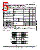
2 / 25 page  LM4312 SNLS265A – MAY 2008 – REVISED MAY 2013 www.ti.com Pin Descriptions No. Description Pin Name I/O, Type(1) of Pins RGB Serializer MPL-2 SERIAL BUS PINS DD0P, DD0M, 4 O, MPL-2 MPL-2 Differential Data Line Driver True (Plus) and Compliment (Minus) Outputs DD1P, DD1M Channel 0 and 1 DCP, DCM 2 O, MPL-2 MPL-2 Differential Clock Line Driver True (Plus) and Compliment (Minus) Outputs SPI INTERFACE and CONFIGURATION PINS SPI_CSX 1 I, SPI_Chip Select Input LVCMOS SPI port is enabled when: SPI_CSX is Low, PD* is High. SPI_SCL 1 I, SPI_Clock Input LVCMOS SPI_DI 1 I, SPI Data Input LVCMOS SPI_DO 1 O, SPI Data Output LVCMOS PD* 1 I, Power Down Mode Input LVCMOS PD* = Low, SER is in SLEEP Mode, SPI Registers are RESET, LUT Data is retained. PD* = High and PCLK = Stopped, SER is in SLEEP Mode, SPI Register settings are retained and LUT data is retained. PD* = High, Device is enabled. RES1 1 I, Tie High LVCMOS TM 1 I Tie Low LVCMOS H = Test Mode (Reserved) VIDEO INTERFACE PINS PCLK 1 I, Pixel Clock Input LVCMOS Video Signals are latched on the RISING edge. R[7:0] 24 I, RGB Data Bus Inputs – Bit 7 is the MSB. G[7:0] LVCMOS 24-bit Mode - use RGB[7:0] B[7:0] 18-bit Mode - use RGB[7:2], tie off RGB[1:0] to GND, do not float. VS 1 I, Vertical Sync. Input LVCMOS This signal is used as a frame start for the Dither block and is required when Dither option is selected. The VS signal is serialized unmodified. HS 1 I, Horizontal Sync. Input LVCMOS DE 1 I, Data Enable Input LVCMOS POWER/GROUND PINS VDD 7 Power Supply Power Supply Pins. All VDD pins must be connect to power supply. 1.6V to 2.0V VSS 1 Ground Ground Pin DAP pad must be connected to Ground. (1) Note: I = Input, O = Output, IO = Input/Output. Do not float unused input pins. These devices have limited built-in ESD protection. The leads should be shorted together or the device placed in conductive foam during storage or handling to prevent electrostatic damage to the MOS gates. 2 Submit Documentation Feedback Copyright © 2008–2013, Texas Instruments Incorporated Product Folder Links: LM4312 |
|
|
リンク URL |
| ALLDATASHEETはお客様のビジネスに役立ちますか? [ DONATE ] |
Alldatasheetは | 広告 | お問い合わせ | プライバシーポリシー | データシートへのリンク | リンク交換 | メーカーリスト All Rights Reserved©Alldatasheet.com |
| Russian : Alldatasheetru.com | Korean : Alldatasheet.co.kr | Spanish : Alldatasheet.es | French : Alldatasheet.fr | Italian : Alldatasheetit.com Portuguese : Alldatasheetpt.com | Polish : Alldatasheet.pl | Vietnamese : Alldatasheet.vn Indian : Alldatasheet.in | Mexican : Alldatasheet.com.mx | British : Alldatasheet.co.uk | New Zealand : Alldatasheet.co.nz |
|
Family Site : ic2ic.com |
icmetro.com |
 Japanese ▼
 English
 Chinese
 German
 Japanese
 Russian
 Korean
 Spanish
 French
 Italian
 Portuguese
 Polish
 Vietnamese
 Indian
 Mexican
 British
 New Zealand