|
データシートサーチシステム |
|
|
データシートサーチシステム |
|
AD8426ACPZ-R7 データシート(PDF) 27 Page - Analog Devices |
|
|
|||||||||||||||||||||||||||||
AD8426ACPZ-R7 データシート(HTML) 27 Page - Analog Devices |
|
|
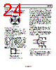
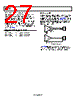
27 / 29 page  AD8426 Rev. 0 | Page 26 of 28 Tips for Best Differential Output Performance Keep trace lengths from resistors to the inverting terminal of the op amp as short as possible. Excessive capacitance at this node can cause the circuit to be unstable. If capacitance cannot be avoided, use lower value resistors. For best linearity and ac performance, a minimum positive supply voltage (+VS) is required. Table 13 shows the minimum supply voltage required for optimum performance, where VCM_MAX indicates the maximum common-mode voltage expected at the input of the AD8426. Table 13. Minimum Positive Supply Voltage Temperature Equation Less than −10°C +VS > (VCM_MAX + VBIAS)/2 + 1.4 V −10°C to +25°C +VS > (VCM_MAX + VBIAS)/2 + 1.25 V More than +25°C +VS > (VCM_MAX + VBIAS)/2 + 1.1 V DRIVING A CABLE All cables have a certain capacitance per unit length, which varies widely with cable type. The capacitive load from the cable may cause peaking in the output response of the AD8426. To reduce the peaking, use a resistor between the AD8426 outputs and the cable (see Figure 71). Because cable capacitance and desired output response vary widely, this resistor is best determined empirically. A good starting point is 50 Ω. AD8426 AD8426 DIFFERENTIAL OUTPUT SINGLE OUTPUT Figure 71. Driving a Cable The AD8426 operates at such a relatively low frequency that transmission line effects are rarely an issue; therefore, the resistor need not match the characteristic impedance of the cable. |
|
リンク URL |
| ALLDATASHEETはお客様のビジネスに役立ちますか? [ DONATE ] |
Alldatasheetは | 広告 | お問い合わせ | プライバシーポリシー | データシートへのリンク | リンク交換 | メーカーリスト All Rights Reserved©Alldatasheet.com |
| Russian : Alldatasheetru.com | Korean : Alldatasheet.co.kr | Spanish : Alldatasheet.es | French : Alldatasheet.fr | Italian : Alldatasheetit.com Portuguese : Alldatasheetpt.com | Polish : Alldatasheet.pl | Vietnamese : Alldatasheet.vn Indian : Alldatasheet.in | Mexican : Alldatasheet.com.mx | British : Alldatasheet.co.uk | New Zealand : Alldatasheet.co.nz |
|
Family Site : ic2ic.com |
icmetro.com |
 Japanese ▼
 English
 Chinese
 German
 Japanese
 Russian
 Korean
 Spanish
 French
 Italian
 Portuguese
 Polish
 Vietnamese
 Indian
 Mexican
 British
 New Zealand