|
データシートサーチシステム |
|
|
データシートサーチシステム |
|
ADR510ART-R2 データシート(PDF) 4 Page - Analog Devices |
|
|
|||||||||||||||||||||||||||||
ADR510ART-R2 データシート(HTML) 4 Page - Analog Devices |
|
|
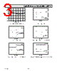
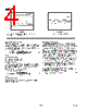
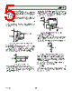
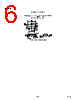
4 / 8 page  REV. 0 –4– ADR510 PARAMETER DEFINITIONS Temperature Coefficient This is the change of output voltage with respect to the operating temperature changes, normalized by the output voltage at 25 °C. This parameter is expressed in ppm/ °C and can be determined with the following equation TCV ppm C VT VT VC T T O OO O ° = ()− () ° ()×− () × 21 21 6 25 10 (1) where: VO(25 °C) = V O at 25 °C VO(T1) = VO at Temperature 1 VO(T2) = VO at Temperature 2 Thermal Hysteresis Thermal hysteresis is defined as the change of output voltage after the device is cycled through the temperature from 25 °C to 0 °C to 70°C and back to 25°C. This is a typical value from a sample of parts put through such a cycle. VV C V V ppm VC V VC O HYS O O TC O HYS OO TC O __ _ _ =° ()− [] = ° ()− ° () × 25 25 25 10 6 (2) where: VO(25 °C) = V O at 25 °C VO_TC = VO at 25 °C after temperature cycle at 25°C to –40°C to 85 °C and back to 25°C APPLICATIONS SECTION The ADR510 is a 1.0 V precision shunt voltage reference. It is designed to operate without an external output capacitor between the positive and negative terminals for stability. An exter- nal capacitor can be used for additional filtering of the supply. As with all shunt voltage references, an external bias resistor (RBIAS) is required between the supply voltage and the ADR510 (see Figure 1). RBIAS sets the current that is required to pass through the load (IL) and the ADR510 (IQ). The load and the supply voltage can vary, thus RBIAS is chosen based on • R BIAS must be small enough to supply the minimum IQ cur- rent to the ADR510 even when the supply voltage is at its minimum and the load current is at its maximum value. • RBIAS also needs to be large enough so that IQ does not exceed 10 mA when the supply voltage is at its maximum and the load current is at its minimum. Given these conditions, RBIAS is determined by the supply voltage (VS), the load and operating current (IL and IQ) of the ADR510, and the ADR510’s output voltage. R(V V ) (I I ) BIAS S OUT L Q =+ –/ (3) TIME (2 s/DIV) DIIN = 100 A VOUT = 50mV/DIV TPC 7. Output Response to 100 µA Input Current Change with 1 µF Capacitor TIME (400ms/DIV) 2 V/DIV TPC 8. 1 Hz to 10 Hz Noise |
|
|
リンク URL |
| ALLDATASHEETはお客様のビジネスに役立ちますか? [ DONATE ] |
Alldatasheetは | 広告 | お問い合わせ | プライバシーポリシー | データシートへのリンク | リンク交換 | メーカーリスト All Rights Reserved©Alldatasheet.com |
| Russian : Alldatasheetru.com | Korean : Alldatasheet.co.kr | Spanish : Alldatasheet.es | French : Alldatasheet.fr | Italian : Alldatasheetit.com Portuguese : Alldatasheetpt.com | Polish : Alldatasheet.pl | Vietnamese : Alldatasheet.vn Indian : Alldatasheet.in | Mexican : Alldatasheet.com.mx | British : Alldatasheet.co.uk | New Zealand : Alldatasheet.co.nz |
|
Family Site : ic2ic.com |
icmetro.com |
 Japanese ▼
 English
 Chinese
 German
 Japanese
 Russian
 Korean
 Spanish
 French
 Italian
 Portuguese
 Polish
 Vietnamese
 Indian
 Mexican
 British
 New Zealand