|
データシートサーチシステム |
|
|
データシートサーチシステム |
|
SMP9317 データシート(PDF) 2 Page - Summit Microelectronics, Inc. |
|
|
|||||||||||||||||||||||||||||
SMP9317 データシート(HTML) 2 Page - Summit Microelectronics, Inc. |
|
|
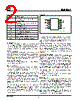
2 / 6 page  2 SMP9317 2031-04 12/4/98 Analog Section The SMP9317 is a 7-bit, voltage output digital-to-analog converter (DAC). The DAC consists of a resistor network that converts a 7-bit value into equivalent analog output voltages in proportion to the applied reference voltage. Reference Inputs The voltage differential between the VL and VH inputs sets the full-scale output voltage range. VL must be equal to or greater than ground (i.e. a positive voltage). VH must be greater than VL and less than or equal to VDD. See table on page 3 for guaranteed operating limits. Output Buffer Amplifier The voltage output is from a precision unity-gain follower that can slew up to 1V/ µs. Digital Interface The interface is designed to emulate a simple up/down counter, but instead of a parallel count output, a ratiometric voltage output is provided. Chip Select ( CS CS CS CS CS) is an active low input. Whenever CS is high the SMP9317 is in standby mode and consumes the least power. This mode is equivalent to a potentiometer that is adjusted to the required setting. When CS is low the SMP9317 will recognize transitions on the INC input and will move the VOUT either toward the VH reference or toward the VL reference depending upon the state of the UP/ DN input. The host may exit an adjustment routine in two ways: deselecting the SMP9317 while INC is low will not per- form a store operation (a subsequent power cycle will recall the original data); deselecting the SMP9317 while INC is high will store the current VOUT setting into non- volatile memory. PINOUT Increment ( INC INC INC INC INC) is an edge triggered input. Whenever CS is low and a high to low transition occurs on the INC input, the VOUT voltage will either move toward VH or VL depending upon the state of the UP/ DN input. UP/Down (UP/ DN DN DN DN DN) is an input that will determine the VOUT movement relative to VH and VL. When CS is low, UP/DN is high and there is a high to low transition on INC, the VOUT voltage will move (1/128th x VH-VL) toward VH. When CS and UP/DN are low, and there is a high to low transition on INC, the VOUT will move (1/128th x VH-VL) toward VL. Power–Up/Power–Down Conditions On power–up the SMP9317 loads the value of EEPROM memory into the wiper position register. The value in the register is changed using the CS, INC, and UP/DN pins. The new data in the register will be lost at power-down unless CS was brought high, with INC high, to initiate a store operation after the last increment or decrement. On the next device power–up, the value of EEPROM memory will be loaded into the wiper position register. During power-up the SMP9317 is write-protected in two ways: 1) A power-on reset, that trips at approximately 2.5V, holds CS and INC high internally. 2) Resistor pull-ups on all logic inputs prevent data change if the inputs are floating. Data Retention The SMP9317 is guaranteed to perform at least 1,000,000 writes to EEPROM before a wear–out condi- tion can occur. After EEPROM wearout, the SMP9317 continues to function as a volatile digital-potentiometer. The wiper position can be changed during powered conditions using the digital interface. However, on power– up the wiper–position will be indeterminate. On shipment from the factory, Summit Microelectronics does not specify any EEPROM memory value. The value must be set by the customer as needed. PIN NAMES Symbol Description INC Increment Input, High to Low Edge Trigger UP/ DN Up/Down Input controlling relative VOUT movement VH V+ reference input GND Analog and Digital Ground VOUT Trimmed Voltage Output VL V- reference input CS Active low chip select input VDD Supply Voltage (2.7V to 5.5V) INC UP/DN VH GND 1 2 3 4 8 7 6 5 2031 ILL1.0 VDD CS VL VOUT |
|
|
リンク URL |
| ALLDATASHEETはお客様のビジネスに役立ちますか? [ DONATE ] |
Alldatasheetは | 広告 | お問い合わせ | プライバシーポリシー | データシートへのリンク | リンク交換 | メーカーリスト All Rights Reserved©Alldatasheet.com |
| Russian : Alldatasheetru.com | Korean : Alldatasheet.co.kr | Spanish : Alldatasheet.es | French : Alldatasheet.fr | Italian : Alldatasheetit.com Portuguese : Alldatasheetpt.com | Polish : Alldatasheet.pl | Vietnamese : Alldatasheet.vn Indian : Alldatasheet.in | Mexican : Alldatasheet.com.mx | British : Alldatasheet.co.uk | New Zealand : Alldatasheet.co.nz |
|
Family Site : ic2ic.com |
icmetro.com |
 Japanese ▼
 English
 Chinese
 German
 Japanese
 Russian
 Korean
 Spanish
 French
 Italian
 Portuguese
 Polish
 Vietnamese
 Indian
 Mexican
 British
 New Zealand