 |
データシートサーチシステム |
|
|
データシートサーチシステム |
|
The question interval is too short.
Please try again in a few seconds.

Hello, Please ask a question about MM54HC190 Datasheet
# Example questions:
➢ The ac electrical characteristics table lists different values for 74hc and 54hc series. what is the primary difference between these two series, as suggested by the provided data?
➢ How does the maximum propagation delay time (tplh, tphl) generally change as the supply voltage (vcc) increases, based on the provided ac electrical characteristics tables?
➢ What is the minimum clock pulse width required for proper operation?
| Part No. | MM54HC190 |
| Manufacturer | NSC |
| Size | 202 Kbytes |
| Pages | 8 pages |
| Description | MM54HC190/MM74HC190 Synchronous Decade Up/Down Counters with Mode Control MM54HC191/MM74HC191 Synchronous Binary Up/Down Counters with Mode Control |

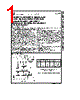
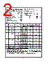


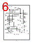


Okay, let's break down this document. It's a datasheet excerpt, likely for a 74HC series logic gate (specifically a counter/divider). Here's a summary, organized for clarity.
1. General Information
️· Part Series: 74HC (and 54HC which is a wider plastic package equivalent) - High-speed CMOS logic.
️· Function: Likely a counter/divider, as indicated by the parameters like "Ripple Clock," "Down/Up," and "Enable."
️· Supply Voltage (VCC): The datasheet details performance for 2.0V, 4.5V, and 6.0V.
️· Operating Temperature: Specifies temperatures for both standard (TA=25°C) and extended commercial (TA= -40 to 85°C) and industrial (TA= -55 to 125°C) ranges.
2. Key Electrical Characteristics - AC Performance (Timing)
️· fMAX (Maximum Clock Frequency):
- 2.0V: 9 MHz
- 4.5V: 30 MHz
- 6.0V: 36 MHz
️· tPLH, tPHL (Maximum Propagation Delay Time): Indicates the time it takes for a signal to propagate through the gate. Multiple values are given depending on the input and output.
- Measured for various input conditions (Data, Clock, Enable) and output combinations (QA, QB, QC, QD, Ripple Clock).
- The values are given for VCC = 2.0V, 4.5V, and 6.0V, as well as the 'typical' (TA=25°C) and guaranteed limits at extended temperatures.
️· tW (Minimum Clock/Clear/Load Input Pulse Width): 10ns. This specifies the minimum duration a clock pulse must be high/low to reliably trigger the gate.
3. Units and Notes
️· All time-related parameters are in nanoseconds (ns).
️· Guaranteed limits are defined under specific test conditions (specified load capacitance, temperature).
️· "Ripple" refers to the cascading of the gate's output to its input to create a clocked sequence.
️· 54HC versions are wider packages for better heat dissipation
Important Considerations and Interpretation:
️· Propagation Delay: Propagation delay is critical for high-speed circuits. A shorter propagation delay means faster operation.
️· Load Capacitance: The datasheet refers to a "specified load capacitance." The propagation delay depends on how much capacitance the output is driving. This datasheet provides delay figures *for a specified load.* If you're driving a different load, you're likely to see different delays.
️· Temperature Effects: As temperature increases, propagation delays typically increase, and maximum frequency decreases.
️· Guaranteed Limits vs. Typical Values: "Guaranteed Limits" are the absolute worst-case performance that the manufacturer guarantees. "Typical" values represent what's likely to be seen under normal operating conditions.
In essence, this document provides engineers with the necessary information to design circuits using this 74HC logic gate, ensuring that timing constraints are met and the circuit operates reliably.
1. General Information
️· Part Series: 74HC (and 54HC which is a wider plastic package equivalent) - High-speed CMOS logic.
️· Function: Likely a counter/divider, as indicated by the parameters like "Ripple Clock," "Down/Up," and "Enable."
️· Supply Voltage (VCC): The datasheet details performance for 2.0V, 4.5V, and 6.0V.
️· Operating Temperature: Specifies temperatures for both standard (TA=25°C) and extended commercial (TA= -40 to 85°C) and industrial (TA= -55 to 125°C) ranges.
2. Key Electrical Characteristics - AC Performance (Timing)
️· fMAX (Maximum Clock Frequency):
- 2.0V: 9 MHz
- 4.5V: 30 MHz
- 6.0V: 36 MHz
️· tPLH, tPHL (Maximum Propagation Delay Time): Indicates the time it takes for a signal to propagate through the gate. Multiple values are given depending on the input and output.
- Measured for various input conditions (Data, Clock, Enable) and output combinations (QA, QB, QC, QD, Ripple Clock).
- The values are given for VCC = 2.0V, 4.5V, and 6.0V, as well as the 'typical' (TA=25°C) and guaranteed limits at extended temperatures.
️· tW (Minimum Clock/Clear/Load Input Pulse Width): 10ns. This specifies the minimum duration a clock pulse must be high/low to reliably trigger the gate.
3. Units and Notes
️· All time-related parameters are in nanoseconds (ns).
️· Guaranteed limits are defined under specific test conditions (specified load capacitance, temperature).
️· "Ripple" refers to the cascading of the gate's output to its input to create a clocked sequence.
️· 54HC versions are wider packages for better heat dissipation
Important Considerations and Interpretation:
️· Propagation Delay: Propagation delay is critical for high-speed circuits. A shorter propagation delay means faster operation.
️· Load Capacitance: The datasheet refers to a "specified load capacitance." The propagation delay depends on how much capacitance the output is driving. This datasheet provides delay figures *for a specified load.* If you're driving a different load, you're likely to see different delays.
️· Temperature Effects: As temperature increases, propagation delays typically increase, and maximum frequency decreases.
️· Guaranteed Limits vs. Typical Values: "Guaranteed Limits" are the absolute worst-case performance that the manufacturer guarantees. "Typical" values represent what's likely to be seen under normal operating conditions.
In essence, this document provides engineers with the necessary information to design circuits using this 74HC logic gate, ensuring that timing constraints are met and the circuit operates reliably.
| Part No. | MM54HC190 |
| Manufacturer | NSC |
| Size | 202 Kbytes |
| Pages | 8 pages |
| Description | MM54HC190/MM74HC190 Synchronous Decade Up/Down Counters with Mode Control MM54HC191/MM74HC191 Synchronous Binary Up/Down Counters with Mode Control |
| ALLDATASHEETはお客様のビジネスに役立ちますか? [ DONATE ] |
Alldatasheetは | 広告 | お問い合わせ | プライバシーポリシー | データシートへのリンク | リンク交換 | メーカーリスト All Rights Reserved©Alldatasheet.com |
| Russian : Alldatasheetru.com | Korean : Alldatasheet.co.kr | Spanish : Alldatasheet.es | French : Alldatasheet.fr | Italian : Alldatasheetit.com Portuguese : Alldatasheetpt.com | Polish : Alldatasheet.pl | Vietnamese : Alldatasheet.vn Indian : Alldatasheet.in | Mexican : Alldatasheet.com.mx | British : Alldatasheet.co.uk | New Zealand : Alldatasheet.co.nz |
|
Family Site : ic2ic.com |
icmetro.com |
 Japanese ▼
  English
 Chinese
 German
 Russian
 Korean
 Spanish
 French
 Italian
 Portuguese
 Polish
 Vietnamese
 Indian
 Mexican
 British
 New Zealand