 |
データシートサーチシステム |
|
|
データシートサーチシステム |
|
The question interval is too short.
Please try again in a few seconds.

Hello, Please ask a question about HM4092 Datasheet
# Example questions:
➢ What is the typical pwm switching frequency?
➢ What is the typical high-side fet on-resistance (rds-hi) with a vbs-vsw of 5v?
➢ What is the threshold voltage for the sleep comparator (vsleep) when the device is in sleep mode?
| Part No. | HM4092 |
| Manufacturer | HMSEMI |
| Size | 759 Kbytes |
| Pages | 14 pages |
| Description | 2.0A, 2-4 cell lithium battery switching charger |



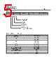


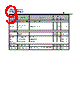



This is a massive amount of information! Let's break down the document into key areas and summarize it. Essentially, it's a datasheet for a battery charging IC (integrated circuit).
1. General Information/Overview:
️· Purpose: The document is a datasheet for a battery charging integrated circuit. This IC is designed to manage the charging process for batteries, likely lithium-ion or similar chemistries.
️· Functionality: The IC provides features like:
- Battery charging
- Over-voltage protection
- Under-voltage protection
- Thermal shutdown
- Current limiting
- Safety timers
- Sleep mode for low power operation
️· Target Applications: Battery-powered devices (portable electronics, power tools, etc.).
2. Electrical Characteristics (Most Important Section - Detailed Breakdown)
This section lists all the electrical parameters and their values. Here's a summary grouped by function, alongside explanations of what they mean:
️· Input Voltage & Current: Defines the voltage and current the IC can handle on its input side (the power source).
️· Battery Charging:
- Charging Voltage: The target voltage for the battery during the charging process.
- Charging Current: The controlled current supplied to the battery. This is a crucial parameter for safety and battery lifespan.
- Charging Profile: This defines the different charging phases (e.g., constant current, constant voltage).
- Charging Current Limits: Ensures the charging current doesn't exceed safe levels.
️· Protection Features:
- UVLO (Under-Voltage Lockout): Prevents the IC from operating if the input voltage is too low, protecting it and the battery.
- OVP (Over-Voltage Protection): Protects the battery from overcharging.
- OTP (Over-Temperature Protection): Shuts down the charging process if the IC gets too hot.
- OCP (Over-Current Protection): Limits the current to prevent damage.
- Short-Circuit Protection: Handles short circuits safely.
️· Sleep Mode:
- Sleep Threshold (VSLEEP): The voltage at which the IC enters a low-power sleep mode.
- Hysteresis (VSLEEP-HYS): A voltage range that prevents the IC from rapidly switching in and out of sleep mode.
️· Thermal Management:
- Thermal Shutdown Temperature (TSHUT): The temperature at which the IC shuts down to prevent overheating.
️· Timers:
- Pre-charge Timer (TPRE-CHARGE): A timer used during the initial phase of charging.
- Taper-charge Timer (TTAPER-CHARGE): A timer used during the final phase of charging.
️· PWM (Pulse Width Modulation):
- Switching Frequency (FSW): Speed of the internal switching for charging/power conversion
- Dead Time (TSW-DEAD): A short period when the switching transistors are both off, preventing shoot-through current.
️· RDS-HI & RDS-LO: On-resistance of internal MOSFETS (used for the high and low side power stages). Lower resistance means more efficient power delivery.
3. Timing Characteristics:
️· This section outlines the timing for various events, such as entering sleep mode, starting the pre-charge phase, and thermal shutdown. These values are critical for understanding the IC's responsiveness.
4. Pin Descriptions:
️· A detailed explanation of each pin on the IC and its function (power input, battery connection, control signals, status indicators, etc.).
5. Summary Table (Most Critical for Quick Reference)
The document includes many tables summarizing key parameters. These tables allow designers to quickly see what values they can expect for various conditions.
Key Takeaways & Design Considerations:
️· Safety is Paramount: The numerous protection features (OVP, UVLO, OTP, OCP) are essential for battery safety and preventing damage.
️· Efficiency: Lower RDS values and optimized PWM design contribute to higher efficiency.
️· Flexibility: Timers and thresholds can often be adjusted to tailor the charging process to specific battery requirements.
️· Thermal Management: Careful consideration of thermal design (heat sinks, airflow) is important to prevent overheating.
️· Pin Configuration: The datasheet provides the pinout for connection to a circuit board.
This is a massive amount of information! Let's break down the document into key areas and summarize it. Essentially, it's a datasheet for a battery charging IC (integrated circuit).
1. General Information/Overview:
️· Purpose: The document is a datasheet for a battery charging integrated circuit. This IC is designed to manage the charging process for batteries, likely lithium-ion or similar chemistries.
️· Functionality: The IC provides features like:
- Battery charging
- Over-voltage protection
- Under-voltage protection
- Thermal shutdown
- Current limiting
- Safety timers
- Sleep mode for low power operation
️· Target Applications: Battery-powered devices (portable electronics, power tools, etc.).
2. Electrical Characteristics (Most Important Section - Detailed Breakdown)
This section lists all the electrical parameters and their values. Here's a summary grouped by function, alongside explanations of what they mean:
️· Input Voltage & Current: Defines the voltage and current the IC can handle on its input side (the power source).
️· Battery Charging:
- Charging Voltage: The target voltage for the battery during the charging process.
- Charging Current: The controlled current supplied to the battery. This is a crucial parameter for safety and battery lifespan.
- Charging Profile: This defines the different charging phases (e.g., constant current, constant voltage).
- Charging Current Limits: Ensures the charging current doesn't exceed safe levels.
️· Protection Features:
- UVLO (Under-Voltage Lockout): Prevents the IC from operating if the input voltage is too low, protecting it and the battery.
- OVP (Over-Voltage Protection): Protects the battery from overcharging.
- OTP (Over-Temperature Protection): Shuts down the charging process if the IC gets too hot.
- OCP (Over-Current Protection): Limits the current to prevent damage.
- Short-Circuit Protection: Handles short circuits safely.
️· Sleep Mode:
- Sleep Threshold (VSLEEP): The voltage at which the IC enters a low-power sleep mode.
- Hysteresis (VSLEEP-HYS): A voltage range that prevents the IC from rapidly switching in and out of sleep mode.
️· Thermal Management:
- Thermal Shutdown Temperature (TSHUT): The temperature at which the IC shuts down to prevent overheating.
️· Timers:
- Pre-charge Timer (TPRE-CHARGE): A timer used during the initial phase of charging.
- Taper-charge Timer (TTAPER-CHARGE): A timer used during the final phase of charging.
️· PWM (Pulse Width Modulation):
- Switching Frequency (FSW): Speed of the internal switching for charging/power conversion
- Dead Time (TSW-DEAD): A short period when the switching transistors are both off, preventing shoot-through current.
️· RDS-HI & RDS-LO: On-resistance of internal MOSFETS (used for the high and low side power stages). Lower resistance means more efficient power delivery.
3. Timing Characteristics:
️· This section outlines the timing for various events, such as entering sleep mode, starting the pre-charge phase, and thermal shutdown. These values are critical for understanding the IC's responsiveness.
4. Pin Descriptions:
️· A detailed explanation of each pin on the IC and its function (power input, battery connection, control signals, status indicators, etc.).
5. Summary Table (Most Critical for Quick Reference)
The document includes many tables summarizing key parameters. These tables allow designers to quickly see what values they can expect for various conditions.
Key Takeaways & Design Considerations:
️· Safety is Paramount: The numerous protection features (OVP, UVLO, OTP, OCP) are essential for battery safety and preventing damage.
️· Efficiency: Lower RDS values and optimized PWM design contribute to higher efficiency.
️· Flexibility: Timers and thresholds can often be adjusted to tailor the charging process to specific battery requirements.
️· Thermal Management: Careful consideration of thermal design (heat sinks, airflow) is important to prevent overheating.
️· Pin Configuration: The datasheet provides the pinout for connection to a circuit board.
| Part No. | HM4092 |
| Manufacturer | HMSEMI |
| Size | 759 Kbytes |
| Pages | 14 pages |
| Description | 2.0A, 2-4 cell lithium battery switching charger |
| ALLDATASHEETはお客様のビジネスに役立ちますか? [ DONATE ] |
Alldatasheetは | 広告 | お問い合わせ | プライバシーポリシー | データシートへのリンク | リンク交換 | メーカーリスト All Rights Reserved©Alldatasheet.com |
| Russian : Alldatasheetru.com | Korean : Alldatasheet.co.kr | Spanish : Alldatasheet.es | French : Alldatasheet.fr | Italian : Alldatasheetit.com Portuguese : Alldatasheetpt.com | Polish : Alldatasheet.pl | Vietnamese : Alldatasheet.vn Indian : Alldatasheet.in | Mexican : Alldatasheet.com.mx | British : Alldatasheet.co.uk | New Zealand : Alldatasheet.co.nz |
|
Family Site : ic2ic.com |
icmetro.com |
 Japanese ▼
  English
 Chinese
 German
 Russian
 Korean
 Spanish
 French
 Italian
 Portuguese
 Polish
 Vietnamese
 Indian
 Mexican
 British
 New Zealand