 |
データシートサーチシステム |
|
|
データシートサーチシステム |
|
The question interval is too short.
Please try again in a few seconds.

Hello, Please ask a question about USB2224 Datasheet
# Example questions:
➢ What is the function of the cf_iordy signal?
➢ What is the purpose of the 'n' symbol in signal names like cf_ncs1, and how does it affect understanding the signal's active state?
➢ Describe the data flow on the cf_d[7:0] and cf_d[15:0] signals during true ide mode operation.
| Part No. | USB2224 |
| Manufacturer | SMSC |
| Size | 167 Kbytes |
| Pages | 20 pages |
| Description | Bus Powered USB2.0 Flash Media Controller |



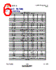

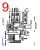
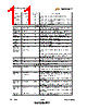


Okay, here's a summary of the provided datasheet excerpts for the SMSC USB2224, a chip designed to interface with flash memory cards (CompactFlash primarily) and provide USB connectivity.
Core Functionality:
️· Flash Memory Support: The chip is designed to interface with CompactFlash (CF) cards in True IDE mode, acting as a bridge between the CF card and a host system (likely via USB).
️· USB Connectivity: While not explicitly detailed in these excerpts, it is implied the chip is used in a USB-based device to enable access to the flash memory cards.
️· IDE Emulation: The chip emulates an IDE (Integrated Drive Electronics) interface for the CF card, allowing a host system to treat the card as a standard hard drive.
Key Features & Details (from the excerpts):
️· CompactFlash Interface: Provides signals for data transfer (CF\_D\[15:0]), control (CF\_nCS0, CF\_nCS1), addressing (CF\_SA0-SA2), interrupt (CF\_IRQ), card detection (CF\_nCD1, CF\_nCD2), and IDE signaling (CF\_IORDY).
️· True IDE Mode: Supports CF cards operating in True IDE mode.
️· Signal Types: The datasheet categorizes signals by type: input, output, bidirectional (I/O), and input pull-up/pull-down (IPU/IPD).
️· Signal Descriptions: Detailed descriptions are provided for each pin, explaining its function and active state (high or low).
️· Buffer Types: Specifies the drive strength of the output buffers (e.g., O8).
What's Not Covered:
️· USB Interface Details: The datasheet excerpt doesn’t describe the USB specifics (USB version, endpoint configuration, etc.).
️· Power Management: There's no information about power-saving features or voltage regulation.
️· Firmware/Software: The excerpts don't mention any firmware or software requirements.
️· Block Diagram Explanation: The block diagram provides a high-level view of the internal architecture but lacks detailed explanations.
In essence, these excerpts focus on the *hardware interface* between the chip and the CompactFlash card. It provides the necessary pin assignments and signal descriptions to design a hardware system that can read and write to the flash memory card.
Core Functionality:
️· Flash Memory Support: The chip is designed to interface with CompactFlash (CF) cards in True IDE mode, acting as a bridge between the CF card and a host system (likely via USB).
️· USB Connectivity: While not explicitly detailed in these excerpts, it is implied the chip is used in a USB-based device to enable access to the flash memory cards.
️· IDE Emulation: The chip emulates an IDE (Integrated Drive Electronics) interface for the CF card, allowing a host system to treat the card as a standard hard drive.
Key Features & Details (from the excerpts):
️· CompactFlash Interface: Provides signals for data transfer (CF\_D\[15:0]), control (CF\_nCS0, CF\_nCS1), addressing (CF\_SA0-SA2), interrupt (CF\_IRQ), card detection (CF\_nCD1, CF\_nCD2), and IDE signaling (CF\_IORDY).
️· True IDE Mode: Supports CF cards operating in True IDE mode.
️· Signal Types: The datasheet categorizes signals by type: input, output, bidirectional (I/O), and input pull-up/pull-down (IPU/IPD).
️· Signal Descriptions: Detailed descriptions are provided for each pin, explaining its function and active state (high or low).
️· Buffer Types: Specifies the drive strength of the output buffers (e.g., O8).
What's Not Covered:
️· USB Interface Details: The datasheet excerpt doesn’t describe the USB specifics (USB version, endpoint configuration, etc.).
️· Power Management: There's no information about power-saving features or voltage regulation.
️· Firmware/Software: The excerpts don't mention any firmware or software requirements.
️· Block Diagram Explanation: The block diagram provides a high-level view of the internal architecture but lacks detailed explanations.
In essence, these excerpts focus on the *hardware interface* between the chip and the CompactFlash card. It provides the necessary pin assignments and signal descriptions to design a hardware system that can read and write to the flash memory card.
| Part No. | USB2224 |
| Manufacturer | SMSC |
| Size | 167 Kbytes |
| Pages | 20 pages |
| Description | Bus Powered USB2.0 Flash Media Controller |
| ALLDATASHEETはお客様のビジネスに役立ちますか? [ DONATE ] |
Alldatasheetは | 広告 | お問い合わせ | プライバシーポリシー | データシートへのリンク | リンク交換 | メーカーリスト All Rights Reserved©Alldatasheet.com |
| Russian : Alldatasheetru.com | Korean : Alldatasheet.co.kr | Spanish : Alldatasheet.es | French : Alldatasheet.fr | Italian : Alldatasheetit.com Portuguese : Alldatasheetpt.com | Polish : Alldatasheet.pl | Vietnamese : Alldatasheet.vn Indian : Alldatasheet.in | Mexican : Alldatasheet.com.mx | British : Alldatasheet.co.uk | New Zealand : Alldatasheet.co.nz |
|
Family Site : ic2ic.com |
icmetro.com |
 Japanese ▼
  English
 Chinese
 German
 Russian
 Korean
 Spanish
 French
 Italian
 Portuguese
 Polish
 Vietnamese
 Indian
 Mexican
 British
 New Zealand