|
データシートサーチシステム |
|
|
データシートサーチシステム |
|
USB2224 データシート(PDF) 10 Page - SMSC Corporation |
|
|
|||||||||||||||||||||||||||||
USB2224 データシート(HTML) 10 Page - SMSC Corporation |
|
|
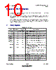
10 / 20 page  Bus Powered USB2.0 Flash Media Controller Datasheet Revision 1.3 (06-13-06) Page 10 SMSC USB2224 DATASHEET Chapter 6 Pin Descriptions This section provides a detailed description of each signal. The signals are arranged in functional groups according to their associated interface. The “n” symbol in the signal name indicates that the active, or asserted state occurs when the signal is at a low voltage level. When “n” is not present before the signal name, the signal is asserted when at the high voltage level. The terms assertion and negation are used exclusively. This is done to avoid confusion when working with a mixture of “active low” and “active high” signal. The term assert, or assertion indicates that a signal is active, independent of whether that level is represented by a high or low voltage. The term negate, or negation indicates that a signal is inactive. 6.1 Pin Descriptions Table 6.1 - Pin Description NAME SYMBOL BUFFER TYPE DESCRIPTION CompactFlash (In True IDE mode) INTERFACE CF Chip Select 1 CF_nCS1 O8 This pin is the active low chip select 1 signal for the CF ATA device CF Chip Select 0 CF_nCS0 O8 This pin is the active low chip select 0 signal for the task file registers of CF ATA device in the True IDE mode. CF Register Address 2 CF_SA2 O8 This pin is the register select address bit 2 for the CF device. CF Register Address 1 CF_SA1 O8 This pin is the register select address bit 1 for the CF device. CF Register Address 0 CF_SA0 O8 This pin is the register select address bit 0 for the CF device. CF Interrupt CF_IRQ IPD This is the active high interrupt request signal from the CF device. CF Data 15-8 CF_D[15:8] I/O8 The bi-directional data signals CF_D15-CF_D8 in True IDE mode data transfer. The bi-directional data signal has an internal weak pull-down resistor. CF Data7-0 CF_D[7:0] I/O8 The bi-directional data signals CF_D7-CF_D0 in the True IDE mode data transfer. In the True IDE Mode, all of task file register operation occur on the CF_D[7:0], while the data transfer is on CF_D[15:0]. The bi-directional data signal has an internal weak pull- down resistor. IO Ready CF_IORDY IPU This pin is active high input signal from CF card. CF Card Detection2 CF_nCD2 IPU This card detection pin is connected to the ground on the CF device, when the CF device is inserted. CF Card Detection1 CF_nCD1 IPU This card detection pin is connected to ground on the CF device, when the CF device is inserted. |
|
|
リンク URL |
| ALLDATASHEETはお客様のビジネスに役立ちますか? [ DONATE ] |
Alldatasheetは | 広告 | お問い合わせ | プライバシーポリシー | データシートへのリンク | リンク交換 | メーカーリスト All Rights Reserved©Alldatasheet.com |
| Russian : Alldatasheetru.com | Korean : Alldatasheet.co.kr | Spanish : Alldatasheet.es | French : Alldatasheet.fr | Italian : Alldatasheetit.com Portuguese : Alldatasheetpt.com | Polish : Alldatasheet.pl | Vietnamese : Alldatasheet.vn Indian : Alldatasheet.in | Mexican : Alldatasheet.com.mx | British : Alldatasheet.co.uk | New Zealand : Alldatasheet.co.nz |
|
Family Site : ic2ic.com |
icmetro.com |
 Japanese ▼
 English
 Chinese
 German
 Japanese
 Russian
 Korean
 Spanish
 French
 Italian
 Portuguese
 Polish
 Vietnamese
 Indian
 Mexican
 British
 New Zealand