 |
データシートサーチシステム |
|
|
データシートサーチシステム |
|
The question interval is too short.
Please try again in a few seconds.

Hello, Please ask a question about AK6004A_02 Datasheet
# Example questions:
➢ What is the minimum write cycle time (twr) for the akm devices, and what can be used to determine when the write cycle is complete?
➢ The datasheet specifies several timing parameters for ac characteristics. what is the purpose of the 'tbuf' parameter, and what does it represent?
➢ What are the two supported i2c communication speeds for the akm devices, and what are the corresponding maximum clock frequencies?
| Part No. | AK6004A_02 |
| Manufacturer | AKM |
| Size | 164 Kbytes |
| Pages | 16 pages |
| Description | I2C bus 4K / 16Kbit Serial CMOS EEPROM |


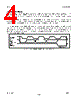


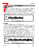
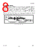



Okay, let's break down the crucial information from this extensive datasheet excerpt, specifically focusing on the requirements for stopping the device and the end of a write cycle, which is what you've asked about. I'm separating it into key points and explaining what they mean for a developer using these devices.
Overall Context: AKM EEPROM Devices (AK6004A/AK6004B and AK6004C)
These are EEPROM devices intended for I2C communication. They have two operating modes:
️· Standard Mode (400kHz): The original mode for early I2C.
️· Fast Mode (4.4MHz): A faster mode.
Stopping the Write Cycle: The "Write Cycle Time" (tWR)
This is *the* key parameter for your question. Here's what the datasheet says, broken down:
️· Definition: `tWR` is the time *from a valid stop condition of a write sequence to the end of the internal program cycle.*
️· Why it matters: During the internal program cycle, the EEPROM *does not acknowledge*. This means your receiving device (the microcontroller or other component sending the data) won't get an ACK from the EEPROM. You *must* wait this `tWR` time before sending another I2C command. Otherwise, the next transmission will be corrupted.
️· Values:
- Fast Mode (4.4MHz): `tWR` = 10 ms
- Standard Mode (400kHz): `tWR` = 10 ms (This is surprisingly long given the lower clock speed!)
️· "ACK Polling": The datasheet mentions "ACK polling." This is an advanced technique where you monitor the ACK line (if available) to determine exactly when the internal program cycle is complete. It lets you *potentially* increase bus throughput by sending another command *sooner* than the full `tWR` time. *However*, using ACK polling correctly is complex and requires careful design.
Summary of Write Cycle Stop Requirements:
️· Always wait 10ms after sending a valid Stop Condition for a Write Sequence, regardless of operating mode (Fast or Standard).
️· You can use ACK polling to potentially reduce this wait time, but it's an advanced technique.
Important Supporting Information (Important for Proper Operation):
️· Stop Condition Validity: The stop condition *must* be valid (meet the timing requirements specified in the I2C standard and the datasheet) for `tWR` to begin. Otherwise, the EEPROM may not recognize the write completion and `tWR` will not start correctly.
️· Fast Mode Timing: If you are using Fast Mode, *all* the Fast Mode timing parameters (tAA, tBUF, tHD:STA, tLOW, tHIGH, tSU:STA, tHD:DAT, tSU:DAT, tR, tF, tSU:STO, tDH) must also be met. Failing to do so can lead to unpredictable behavior.
️· Bus Free Time (tBUF): After a Stop Condition, you must wait at least `tBUF` before starting the next transmission. Fast mode requires a shorter free time.
In essence: This datasheet excerpt instructs you to wait 10 milliseconds after the write completes and meet other timing specifications for consistent writes to the EEPROM.
Overall Context: AKM EEPROM Devices (AK6004A/AK6004B and AK6004C)
These are EEPROM devices intended for I2C communication. They have two operating modes:
️· Standard Mode (400kHz): The original mode for early I2C.
️· Fast Mode (4.4MHz): A faster mode.
Stopping the Write Cycle: The "Write Cycle Time" (tWR)
This is *the* key parameter for your question. Here's what the datasheet says, broken down:
️· Definition: `tWR` is the time *from a valid stop condition of a write sequence to the end of the internal program cycle.*
️· Why it matters: During the internal program cycle, the EEPROM *does not acknowledge*. This means your receiving device (the microcontroller or other component sending the data) won't get an ACK from the EEPROM. You *must* wait this `tWR` time before sending another I2C command. Otherwise, the next transmission will be corrupted.
️· Values:
- Fast Mode (4.4MHz): `tWR` = 10 ms
- Standard Mode (400kHz): `tWR` = 10 ms (This is surprisingly long given the lower clock speed!)
️· "ACK Polling": The datasheet mentions "ACK polling." This is an advanced technique where you monitor the ACK line (if available) to determine exactly when the internal program cycle is complete. It lets you *potentially* increase bus throughput by sending another command *sooner* than the full `tWR` time. *However*, using ACK polling correctly is complex and requires careful design.
Summary of Write Cycle Stop Requirements:
️· Always wait 10ms after sending a valid Stop Condition for a Write Sequence, regardless of operating mode (Fast or Standard).
️· You can use ACK polling to potentially reduce this wait time, but it's an advanced technique.
Important Supporting Information (Important for Proper Operation):
️· Stop Condition Validity: The stop condition *must* be valid (meet the timing requirements specified in the I2C standard and the datasheet) for `tWR` to begin. Otherwise, the EEPROM may not recognize the write completion and `tWR` will not start correctly.
️· Fast Mode Timing: If you are using Fast Mode, *all* the Fast Mode timing parameters (tAA, tBUF, tHD:STA, tLOW, tHIGH, tSU:STA, tHD:DAT, tSU:DAT, tR, tF, tSU:STO, tDH) must also be met. Failing to do so can lead to unpredictable behavior.
️· Bus Free Time (tBUF): After a Stop Condition, you must wait at least `tBUF` before starting the next transmission. Fast mode requires a shorter free time.
In essence: This datasheet excerpt instructs you to wait 10 milliseconds after the write completes and meet other timing specifications for consistent writes to the EEPROM.
| Part No. | AK6004A_02 |
| Manufacturer | AKM |
| Size | 164 Kbytes |
| Pages | 16 pages |
| Description | I2C bus 4K / 16Kbit Serial CMOS EEPROM |
| ALLDATASHEETはお客様のビジネスに役立ちますか? [ DONATE ] |
Alldatasheetは | 広告 | お問い合わせ | プライバシーポリシー | データシートへのリンク | リンク交換 | メーカーリスト All Rights Reserved©Alldatasheet.com |
| Russian : Alldatasheetru.com | Korean : Alldatasheet.co.kr | Spanish : Alldatasheet.es | French : Alldatasheet.fr | Italian : Alldatasheetit.com Portuguese : Alldatasheetpt.com | Polish : Alldatasheet.pl | Vietnamese : Alldatasheet.vn Indian : Alldatasheet.in | Mexican : Alldatasheet.com.mx | British : Alldatasheet.co.uk | New Zealand : Alldatasheet.co.nz |
|
Family Site : ic2ic.com |
icmetro.com |
 Japanese ▼
  English
 Chinese
 German
 Russian
 Korean
 Spanish
 French
 Italian
 Portuguese
 Polish
 Vietnamese
 Indian
 Mexican
 British
 New Zealand