 |
データシートサーチシステム |
|
|
データシートサーチシステム |
|
The question interval is too short.
Please try again in a few seconds.

Hello, Please ask a question about CD54HC190_15 Datasheet
# Example questions:
➢ What is the primary function of the 'hc190 and 'hc191/hct191 flip-flops?
➢ What happens to 'illegal states' in bcd counters using the 'hc190 and 'hc191/hct191?
➢ Describe the typical sequence illustrated in the documents for the 'hc190 counter, starting with the initial loading state.
| Part No. | CD54HC190_15 |
| Manufacturer | TI1 |
| Size | 1Mb |
| Pages | 31 pages |
| Description | SYNCHORONOUS UP/DOWN COUNTERS WITH DOWN/UP MODE CONTROL |










# CD54/74HC190/191/HCT191 Counters
## Description & Ordering Information
️· Function: Asynchronously presettable BCD decade (HC190) or binary (HC191/HCT191) counters.
️· Presetting: Accomplished via low asynchronous parallel load (LOAD) input.
️· Counting: Occurs when LOAD is high, Count Enable (CTEN) is low, and Down/Up (D/U) input is high (down) or low (up).
️· Clocking: Synchronous operation with low-to-high clock transition.
️· Ordering: Multiple package options are available (PDIP, SOIC, TSSOP, CDIP) with varying temperature ranges (-55°C to 125°C).
️· Resource: Package details, thermal data and PCB design guidelines available at www.ti.com/sc/package.
## Functional Details
️· Inputs: LOAD, CTEN, D/U, Clock.
️· Outputs: QA, QB, QC, QD, MAX/MIN (for cascading), RCO (Ripple Clock).
️· MAX/MIN Output: Indicates overflow/underflow for look-ahead carry.
️· Illegal State Correction: Decade counter (HC190) corrects illegal states in one or two counts.
## Logic Diagrams & Flip-Flop
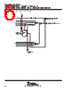
️· Detailed logic diagrams for HC190 and HC191/HCT191 are provided.
️· Illustration of the internal flip-flop structure.
## Typical Operation (HC190)
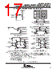
️· Sequence: Load (BCD 7), Count Up (8, 9, 0, 1, 2), Inhibit, Count Down (1, 0, 9, 8, 7).
️· Control Signals: Illustrates the use of LOAD, Preset input data, Clock Enable, and Terminal Count/Ripple Clock.
## Typical Operation (HC191/HCT191)
️· Sequence: Load (binary 13), Count Up (14, 15, 0, 1, 2), Inhibit, Count Down (1, 0, 15, 14, 13).
## Figures
️· Figure 1: HC190 Synchronous n-Stage Counter with Parallel Gated Terminal Count.
️· Figure 2: HC191/HCT191 Synchronous n-Stage Counter with Parallel Gated Terminal Count.
️· Figure 3: HC190 State Diagram.
# CD54/74HC190/191/HCT191 Counters
## Description & Ordering Information
️· Function: Asynchronously presettable BCD decade (HC190) or binary (HC191/HCT191) counters.
️· Presetting: Accomplished via low asynchronous parallel load (LOAD) input.
️· Counting: Occurs when LOAD is high, Count Enable (CTEN) is low, and Down/Up (D/U) input is high (down) or low (up).
️· Clocking: Synchronous operation with low-to-high clock transition.
️· Ordering: Multiple package options are available (PDIP, SOIC, TSSOP, CDIP) with varying temperature ranges (-55°C to 125°C).
️· Resource: Package details, thermal data and PCB design guidelines available at www.ti.com/sc/package.
## Functional Details
️· Inputs: LOAD, CTEN, D/U, Clock.
️· Outputs: QA, QB, QC, QD, MAX/MIN (for cascading), RCO (Ripple Clock).
️· MAX/MIN Output: Indicates overflow/underflow for look-ahead carry.
️· Illegal State Correction: Decade counter (HC190) corrects illegal states in one or two counts.
## Logic Diagrams & Flip-Flop
️· Detailed logic diagrams for HC190 and HC191/HCT191 are provided.
️· Illustration of the internal flip-flop structure.
## Typical Operation (HC190)
️· Sequence: Load (BCD 7), Count Up (8, 9, 0, 1, 2), Inhibit, Count Down (1, 0, 9, 8, 7).
️· Control Signals: Illustrates the use of LOAD, Preset input data, Clock Enable, and Terminal Count/Ripple Clock.
## Typical Operation (HC191/HCT191)
️· Sequence: Load (binary 13), Count Up (14, 15, 0, 1, 2), Inhibit, Count Down (1, 0, 15, 14, 13).
## Figures
️· Figure 1: HC190 Synchronous n-Stage Counter with Parallel Gated Terminal Count.
️· Figure 2: HC191/HCT191 Synchronous n-Stage Counter with Parallel Gated Terminal Count.
️· Figure 3: HC190 State Diagram.
| Part No. | CD54HC190_15 |
| Manufacturer | TI1 |
| Size | 1Mb |
| Pages | 31 pages |
| Description | SYNCHORONOUS UP/DOWN COUNTERS WITH DOWN/UP MODE CONTROL |
| ALLDATASHEETはお客様のビジネスに役立ちますか? [ DONATE ] |
Alldatasheetは | 広告 | お問い合わせ | プライバシーポリシー | データシートへのリンク | リンク交換 | メーカーリスト All Rights Reserved©Alldatasheet.com |
| Russian : Alldatasheetru.com | Korean : Alldatasheet.co.kr | Spanish : Alldatasheet.es | French : Alldatasheet.fr | Italian : Alldatasheetit.com Portuguese : Alldatasheetpt.com | Polish : Alldatasheet.pl | Vietnamese : Alldatasheet.vn Indian : Alldatasheet.in | Mexican : Alldatasheet.com.mx | British : Alldatasheet.co.uk | New Zealand : Alldatasheet.co.nz |
|
Family Site : ic2ic.com |
icmetro.com |
 Japanese ▼
  English
 Chinese
 German
 Russian
 Korean
 Spanish
 French
 Italian
 Portuguese
 Polish
 Vietnamese
 Indian
 Mexican
 British
 New Zealand