|
データシートサーチシステム |
|
|
データシートサーチシステム |
|
EM8800AG データシート(PDF) 7 Page - Excelliance MOS Corp. |
|
|
|||||||||||||||||||||||||||||
EM8800AG データシート(HTML) 7 Page - Excelliance MOS Corp. |
|
|
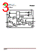
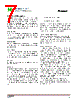
7 / 8 page  2011/09/06 Rev.A.3 7 EM8800A Functional Description EM8800A is a constant off time current mode controller. The PWMD pin enables the user to use a PWM signal to modulate the switching pattern and adjust the average luminosity. The LD/SS pin enables the user to set peak current by adjust the voltage of this pin. A capacitor connected to the LD/SS pin sets the soft start period. Supply Voltage The VCC pin provides the bias supply of EM8800A control circuit, as well as MOSFET’s gate. A minimum 0.1uF ceramic capacitor is recommended to bypass the supply voltage. Power ON Reset To let EM8800A start to operation, VCC voltage must be higher than its POR voltage. Typical POR voltage is 9.75V. Start Up Delay When VCC reaches POR threshold, start-up-delay timer begins to count. When start-up-delay is finished, the current source of LD/SS pin is enabled and the soft-start sequence begins. Soft Start A capacitor connected to the LD/SS pin sets the soft start period. Dimming The device is able to perform both linear and PWM dimming. Two separate inputs are provided (LD/SS pin for linear dimming, PWMD pin for PWM dimming). The two functions can be used simultaneously and independently to one another. Linear dimming can be performed by applying a dc voltage between 0.3V and 3V. This voltage is internally processed, generating the reference level VCS_LD. The relationship between VLD and VCS_LD is: VCS_LD=VLD/3, when VLD>0.3V VCS_LD=0.1V, when VLD<=0.3V PWM dimming can be achieved by driving the PWMD pin with a low frequency square wave signal. When the PWMD signal is lower than 0.8V, switching is inhibited. When the PWMD signal is higher than 2V, the switching is enabled. Constant Off-Time Generator The off-time generator begins at the end of each on time. Once the off time generator has elapsed, it begins the next GATE pulse. The off-time is programmed by connecting a resistor from the TOFF pin to ground. Protections and Fault Flag In case the LED string fails short, the inductor current will rise cycle by cycle without control. To prevent the current from exceeding levels that might lead to catastrophic failure of the power MOSFET, EM8800A detects if VCS exceeds 1.5V. If this occurs for eight consecutive switching cycles, a latched shutdown function is tripped: the device is stopped in an idle state and it is necessary to recycle its supply voltage to make it restart. In case the LED string fails open, the current will drop to zero and the inductor current will never reach the programmed level. To detect this situation, an internal timer checks the ON time of the power MOSFET and, if it exceeds 30us for eight consecutive switching cycles, a latched shutdown function is tripped: the device is stopped in an idle state and it is necessary to recycle its supply voltage to make it restart. In either case, the activation of the protection functions is signaled by FAULT pin asserted high, becoming a 5V voltage source able to provide up to 5mA source current. |
|
|
リンク URL |
| ALLDATASHEETはお客様のビジネスに役立ちますか? [ DONATE ] |
Alldatasheetは | 広告 | お問い合わせ | プライバシーポリシー | データシートへのリンク | リンク交換 | メーカーリスト All Rights Reserved©Alldatasheet.com |
| Russian : Alldatasheetru.com | Korean : Alldatasheet.co.kr | Spanish : Alldatasheet.es | French : Alldatasheet.fr | Italian : Alldatasheetit.com Portuguese : Alldatasheetpt.com | Polish : Alldatasheet.pl | Vietnamese : Alldatasheet.vn Indian : Alldatasheet.in | Mexican : Alldatasheet.com.mx | British : Alldatasheet.co.uk | New Zealand : Alldatasheet.co.nz |
|
Family Site : ic2ic.com |
icmetro.com |
 Japanese ▼
 English
 Chinese
 German
 Japanese
 Russian
 Korean
 Spanish
 French
 Italian
 Portuguese
 Polish
 Vietnamese
 Indian
 Mexican
 British
 New Zealand