|
データシートサーチシステム |
|
|
データシートサーチシステム |
|
ADL5358ACPZ-R2 データシート(PDF) 19 Page - Analog Devices |
|
|
|||||||||||||||||||||||||||||
ADL5358ACPZ-R2 データシート(HTML) 19 Page - Analog Devices |
|
|
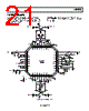
19 / 24 page  ADL5358 Rev. 0 | Page 19 of 24 APPLICATIONS INFORMATION BASIC CONNECTIONS The ADL5358 mixer is designed to downconvert radio frequencies (RF) primarily between 500 MHz and 1700 MHz to lower intermediate frequencies (IF) between 30 MHz and 450 MHz. Figure 53 depicts the basic connections of the mixer. It is recommended to ac-couple the RF and LO input ports to prevent non-zero dc voltages from damaging the RF balun or LO input circuit. The RFIN matching network consists of a series 8 pF capacitor to provide the optimized RF input return loss for the desired frequency band. IF PORT The mixer differential IF interface requires pull-up choke inductors to bias the open-collector outputs and to set the output match. The shunting impedance of the choke inductors used to couple dc current into the IF amplifier should be selected to provide the desired output return loss. The real part of the output impedance is approximately 200 Ω, as seen in Figure 30, which matches many commonly used SAW filters without the need for a transformer. This results in a voltage conversion gain that is approximately 6 dB higher than the power conversion gain, as shown in Table 3. When a 50 Ω output impedance is needed, use a 4:1 impedance transformer, as shown in Figure 53. BIAS RESISTOR SELECTION The IF bias resistors (R1 and R4) and LO bias resistors (R2 and R5) are used to adjust the bias current of the integrated amplifiers at the IF and LO terminals. It is necessary to have a sufficient amount of current to bias both the internal IF and LO amplifiers to optimize dc current vs. optimum IIP3 performance. Figure 41, Figure 43, and Figure 44 provide the reference for the bias resistor selection when lower power consumption is preferred at the expense of conversion gain and IP3 performance. MIXER VGS CONTROL DAC The ADL5358 features three logic control pins, VGS0 (Pin 24), VGS1 (Pin 25), and VGS2 (Pin 26), that allow programmability for internal gate-to-source voltages for optimizing mixer performance over desired frequency bands. The evaluation board defaults VGS0, VGS1, and VGS2 to ground. Power conversion gain, NF, IIP3, and input P1dB can be optimized, as shown in Figure 39 and Figure 40. |
|
|
リンク URL |
| ALLDATASHEETはお客様のビジネスに役立ちますか? [ DONATE ] |
Alldatasheetは | 広告 | お問い合わせ | プライバシーポリシー | データシートへのリンク | リンク交換 | メーカーリスト All Rights Reserved©Alldatasheet.com |
| Russian : Alldatasheetru.com | Korean : Alldatasheet.co.kr | Spanish : Alldatasheet.es | French : Alldatasheet.fr | Italian : Alldatasheetit.com Portuguese : Alldatasheetpt.com | Polish : Alldatasheet.pl | Vietnamese : Alldatasheet.vn Indian : Alldatasheet.in | Mexican : Alldatasheet.com.mx | British : Alldatasheet.co.uk | New Zealand : Alldatasheet.co.nz |
|
Family Site : ic2ic.com |
icmetro.com |
 Japanese ▼
 English
 Chinese
 German
 Japanese
 Russian
 Korean
 Spanish
 French
 Italian
 Portuguese
 Polish
 Vietnamese
 Indian
 Mexican
 British
 New Zealand