|
データシートサーチシステム |
|
|
データシートサーチシステム |
|
MCP6401RT-E データシート(PDF) 11 Page - Microchip Technology |
|
|
|||||||||||||||||||||||||||||
MCP6401RT-E データシート(HTML) 11 Page - Microchip Technology |
|
|
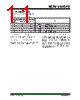
11 / 28 page  © 2009 Microchip Technology Inc. DS22229A-page 11 MCP6401/1R/1U 3.0 PIN DESCRIPTIONS Descriptions of the pins are listed in Table 3-1. TABLE 3-1: PIN FUNCTION TABLE 3.1 Analog Output (VOUT) The output pin is low-impedance voltage source. 3.2 Analog Inputs (VIN+, VIN-) The non-inverting and inverting inputs are high- impedance CMOS inputs with low bias currents. 3.3 Power Supply Pin (VDD, VSS) The positive power supply (VDD) is 1.8V to 6.0V higher than the negative power supply (VSS). For normal operation, the other pins are at voltages between VSS and VDD. Typically, these parts are used in a single (positive) supply configuration. In this case, VSS is connected to ground and VDD is connected to the supply. VDD will need bypass capacitors. MCP6401 MCP6401R MCP6401U Symbol Description SC70-5, SOT-23-5 SOT-23-5 SOT-23-5 11 4 VOUT Analog Output 25 2 VSS Negative Power Supply 3 31VIN+ Non-inverting Input 44 3 VIN– Inverting Input 52 5 VDD Positive Power Supply |
|
|
リンク URL |
| ALLDATASHEETはお客様のビジネスに役立ちますか? [ DONATE ] |
Alldatasheetは | 広告 | お問い合わせ | プライバシーポリシー | データシートへのリンク | リンク交換 | メーカーリスト All Rights Reserved©Alldatasheet.com |
| Russian : Alldatasheetru.com | Korean : Alldatasheet.co.kr | Spanish : Alldatasheet.es | French : Alldatasheet.fr | Italian : Alldatasheetit.com Portuguese : Alldatasheetpt.com | Polish : Alldatasheet.pl | Vietnamese : Alldatasheet.vn Indian : Alldatasheet.in | Mexican : Alldatasheet.com.mx | British : Alldatasheet.co.uk | New Zealand : Alldatasheet.co.nz |
|
Family Site : ic2ic.com |
icmetro.com |
 Japanese ▼
 English
 Chinese
 German
 Japanese
 Russian
 Korean
 Spanish
 French
 Italian
 Portuguese
 Polish
 Vietnamese
 Indian
 Mexican
 British
 New Zealand