|
データシートサーチシステム |
|
|
データシートサーチシステム |
|
AS1910Z-T データシート(PDF) 10 Page - ams AG |
|
|
|||||||||||||||||||||||||||||
AS1910Z-T データシート(HTML) 10 Page - ams AG |
|
|
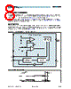
10 / 15 page  www.austriamicrosystems.com Revision 1.00 10 - 15 AS1910 - AS1915 Data Sheet - D e t a i l e d D e s c r i p t i o n Watchdog Input The integrated watchdog feature can be used to monitor processor activity via pin WDI, and can detect pulses as short as 50ns. The watchdog requires that the processor toggle the watchdog logic input at regular intervals, within a speci- fied minimum timeout period (1.5s, typ). A reset is asserted for the reset timeout period. As long as reset is asserted, the timer remains cleared and is not incremented. When reset is deasserted, the watchdog timer starts counting (Figure 11). Note: The watchdog timer can be cleared with a reset pulse or by toggling WDI. Figure 13. Watchdog Timing Relationship The watchdog is internally driven low during most (87.5%) of the watchdog timeout period (see tWD on page 6) and high for the rest of the watchdog timeout period. When pin WDI is left unconnected, this internal driver clears the watchdog timer every 1.4s. When WDI is tri-stated or is not connected, the maximum allowable leakage current is 10µA and the maximum allowable load capacitance is 200pF. Note: The watchdog function can be disabled by leaving pin WDI unconnected or connecting it to a tri-state output buffer. Manual Reset Input The active-low pin MRN is used to force a manual reset. This input can be driven by CMOS logic levels or with open- drain collector outputs. Pulling MRN low asserts a reset which will remain asserted as long as MRN is kept low, and for the timeout period (see tRP on page 5) after MRN goes high (140ms min). The manual reset circuitry has an internal 50k Ω pullup resistor, thus it can be left open if not used. To create a manual-reset circuit, connect a normally open momentary switch from pin MRN to GND (see Figure 1 on page 1); external debounce circuitry is not required in this configuration. If MRN is driven via long cables or the device is used in a noisy environment, a 0.1µF capacitor between pin MRN and GND will provide additional noise immunity. tRST The RESET signal is the inverse of the RESETN signal. tWD VCC RESETN WDI tRP tRP |
|
|
リンク URL |
| ALLDATASHEETはお客様のビジネスに役立ちますか? [ DONATE ] |
Alldatasheetは | 広告 | お問い合わせ | プライバシーポリシー | データシートへのリンク | リンク交換 | メーカーリスト All Rights Reserved©Alldatasheet.com |
| Russian : Alldatasheetru.com | Korean : Alldatasheet.co.kr | Spanish : Alldatasheet.es | French : Alldatasheet.fr | Italian : Alldatasheetit.com Portuguese : Alldatasheetpt.com | Polish : Alldatasheet.pl | Vietnamese : Alldatasheet.vn Indian : Alldatasheet.in | Mexican : Alldatasheet.com.mx | British : Alldatasheet.co.uk | New Zealand : Alldatasheet.co.nz |
|
Family Site : ic2ic.com |
icmetro.com |
 Japanese ▼
 English
 Chinese
 German
 Japanese
 Russian
 Korean
 Spanish
 French
 Italian
 Portuguese
 Polish
 Vietnamese
 Indian
 Mexican
 British
 New Zealand