|
データシートサーチシステム |
|
|
データシートサーチシステム |
|
AP7335 データシート(PDF) 11 Page - Diodes Incorporated |
|
|
|||||||||||||||||||||||||||||
AP7335 データシート(HTML) 11 Page - Diodes Incorporated |
|
|
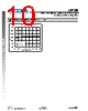
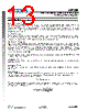
11 / 18 page  AP7335 300mA, Low Quiescent Current, Fast Transient Low Dropout Linear Regulator AP7335 Document number: DS32259 Rev. 1 - 2 11 of 18 www.diodes.com July 2010 © Diodes Incorporated Application Note Input Capacitor A 1 μF ceramic capacitor is recommended between IN and GND pins to decouple input power supply glitch and noise. The amount of the capacitance may be increased without limit. This input capacitor must be located as close as possible to the device to assure input stability and reduce noise. For PCB layout, a wide copper trace is required for both IN and GND pins. A lower ESR capacitor type allows the use of less capacitance, while higher ESR type requires more capacitance. Output Capacitor The output capacitor is required to stabilize and improve the transient response of the LDO. The AP7335 is stable with very small ceramic output capacitors. Using a ceramic capacitor value that is at least 1 μF with ESR > 15mΩ on the output ensures stability. Higher capacitance values help to improve line and load transient response. The output capacitance may be increased to keep low undershoot and overshoot. Output capacitor must be placed as close as possible to OUT and GND pins. Region of Stable COUT ESR vs. Load Current 0.001 0.01 0.1 1 10 100 0 50 100 150 200 250 300 Load Current (mA) Unstable Range Stable Range Unstable Range VIN=4.3V CIN=COUT=1μF |
|
|
リンク URL |
| ALLDATASHEETはお客様のビジネスに役立ちますか? [ DONATE ] |
Alldatasheetは | 広告 | お問い合わせ | プライバシーポリシー | データシートへのリンク | リンク交換 | メーカーリスト All Rights Reserved©Alldatasheet.com |
| Russian : Alldatasheetru.com | Korean : Alldatasheet.co.kr | Spanish : Alldatasheet.es | French : Alldatasheet.fr | Italian : Alldatasheetit.com Portuguese : Alldatasheetpt.com | Polish : Alldatasheet.pl | Vietnamese : Alldatasheet.vn Indian : Alldatasheet.in | Mexican : Alldatasheet.com.mx | British : Alldatasheet.co.uk | New Zealand : Alldatasheet.co.nz |
|
Family Site : ic2ic.com |
icmetro.com |
 Japanese ▼
 English
 Chinese
 German
 Japanese
 Russian
 Korean
 Spanish
 French
 Italian
 Portuguese
 Polish
 Vietnamese
 Indian
 Mexican
 British
 New Zealand