|
データシートサーチシステム |
|
|
データシートサーチシステム |
|
TPS65232 データシート(PDF) 10 Page - Texas Instruments |
|
|
|||||||||||||||||||||||||||||
TPS65232 データシート(HTML) 10 Page - Texas Instruments |
|
|
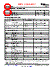
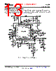
10 / 31 page  V3p3 V3p3 (1) (2) EN_BCKx BUCKENABLE 6uA Enable Threshold BUCK A Enable BUCKB Enable BUCKC Enable Time Delaytime = 0.2ms/nF 1.2V (1) Connect EN_BCKx pin to V3P3 to follow the default power-up sequence or (2) Connect a capacitor from EN_BCKx to GND to generate a custom power-up sequence. TPS65232 SLVSA42 – FEBRUARY 2010 www.ti.com ELECTRICAL CHARACTERISTICS (continued) VIN = 12 V ±5%, VINB2, VINB3 = 5 V ±5%, TJ = 0°C to 150°C (unless otherwise noted) PARAMETER TEST CONDITIONS MIN TYP MAX UNIT SOFT START (BUCK1, 2, and 3) ISS Soft start current source 2 mA VSS, MAX Soft start ramp voltage Ramp end 0.8 V CSS Soft start capacitor tSS = 0.4 ms/nF 2 3.3 4.7 nF SSDONE_BK Deglitch time 2.5 ms SSDONE_DCH SS discharge time 500 ms THERMAL SHUTDOWN Thot Thermal warning 120 °C Ttrip Thermal s/d trip point 160 °C Thyst Thermal s/d hysteresis 20 °C POWER-UP SEQUENCING ON/OFF control and power sequencing of the three buck regulators is controlled through EN_BCK1, EN_BCK2, and EN_BCK3 enable pins. Each pin is internally connected to a 6-mA constant-current source and monitored by a comparator with Schmitt trigger input with defined threshold. Connecting EN_BCKn pin to ground disables BUCKn and connecting EN_BCKn to V3p3 will enable the respective buck without delay. If more than one buck enable pin is connected to V3p3 the default startup sequence is BUCK1, BUCK2, BUCK3 and the minimum startup delay between rails is the soft-start time (typical 1.5 ms) plus 1 ms. To create a startup-sequence different from the default, capacitors are connected between the EN_BUCKn pins and ground. At power-up the capacitors are first discharged and then charged to V3p3 level by internal current sources (6 mA typical) creating a constant-slope voltage ramp. A regulator is enabled when its EN pin voltage crosses the enable threshold (typical 1.2 V). A delay of 0.2 ms is generated for each 1-nF of capacitance connected to the enable pin. If two enable pins are pulled high while the third regulator is starting up, the default sequence will be applied to enable the remaining two regulators. To override default power-up sequence it is recommended that delay times differ by more than the soft-start time (typical 1.3 ms) plus 1 ms. Figure 1. Customizing the Power-Up Sequence 10 Submit Documentation Feedback Copyright © 2010, Texas Instruments Incorporated Product Folder Link(s): TPS65232 Not Recommended for New Designs |
|
リンク URL |
| ALLDATASHEETはお客様のビジネスに役立ちますか? [ DONATE ] |
Alldatasheetは | 広告 | お問い合わせ | プライバシーポリシー | データシートへのリンク | リンク交換 | メーカーリスト All Rights Reserved©Alldatasheet.com |
| Russian : Alldatasheetru.com | Korean : Alldatasheet.co.kr | Spanish : Alldatasheet.es | French : Alldatasheet.fr | Italian : Alldatasheetit.com Portuguese : Alldatasheetpt.com | Polish : Alldatasheet.pl | Vietnamese : Alldatasheet.vn Indian : Alldatasheet.in | Mexican : Alldatasheet.com.mx | British : Alldatasheet.co.uk | New Zealand : Alldatasheet.co.nz |
|
Family Site : ic2ic.com |
icmetro.com |
 Japanese ▼
 English
 Chinese
 German
 Japanese
 Russian
 Korean
 Spanish
 French
 Italian
 Portuguese
 Polish
 Vietnamese
 Indian
 Mexican
 British
 New Zealand