|
データシートサーチシステム |
|
|
データシートサーチシステム |
|
ADT7320UCPZ-R2 データシート(PDF) 6 Page - Analog Devices |
|
|
|||||||||||||||||||||||||||||
ADT7320UCPZ-R2 データシート(HTML) 6 Page - Analog Devices |
|
|
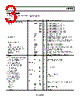
6 / 24 page  ADT7320 Data Sheet Rev. 0 | Page 6 of 24 PIN CONFIGURATION AND FUNCTION DESCRIPTIONS 12 11 10 1 3 4 VDD 17 EPAD GND CT 9 INT SCLK DIN 2 DOUT CS ADT7320 TOP VIEW (Not to Scale) NOTES 1. NC = NO CONNECT. DO NOT CONNECT TO THIS PIN. THE NC PIN IS NOT BONDED TO THE DIE INTERNALLY. 2. TO ENSURE CORRECT OPERATION, THE EXPOSED PAD SHOULD EITHER BE LEFT FLOATING OR CONNECTED TO GROUND. Figure 3. Pin Configuration Table 4. Pin Function Descriptions Pin No. Mnemonic Description 1 SCLK Serial Clock Input. The serial clock is used to clock data into and out of any register of the ADT7320. 2 DOUT Serial Data Output. Data is clocked out on the SCLK falling edge and is valid on the SCLK rising edge. 3 DIN Serial Data Input. Serial data to be loaded to the control registers of the part is provided on this input. Data is clocked into the registers on the rising edge of SCLK. 4 CS Chip Select Input. The device is enabled when this input is low. The device is disabled when this pin is high. 5 NC No Connect. Do not connect to this pin. The NC pin is not bonded to the die internally. 6 NC No Connect. Do not connect to this pin. The NC pin is not bonded to the die internally. 7 NC No Connect. Do not connect to this pin. The NC pin is not bonded to the die internally. 8 NC No Connect. Do not connect to this pin. The NC pin is not bonded to the die internally. 9 INT Overtemperature and Undertemperature Interrupt. Logic output. Power-up default setting is as an active low comparator interrupt. Open-drain configuration. A pull-up resistor is required, typically 10 kΩ. 10 CT Critical Overtemperature Interrupt. Logic output. Power-up default polarity is active low. Open-drain configuration. A pull-up resistor is required, typically 10 kΩ. 11 GND Analog and Digital Ground. 12 VDD Positive Supply Voltage (2.7 V to 5.5 V). Decouple the supply with a 0.1 μF ceramic capacitor to GND. 13 NC No Connect. Do not connect to this pin. The NC pin is not bonded to the die internally. 14 NC No Connect. Do not connect to this pin. The NC pin is not bonded to the die internally. 15 NC No Connect. Do not connect to this pin. The NC pin is not bonded to the die internally. 16 NC No Connect. Do not connect to this pin. The NC pin is not bonded to the die internally. 17 EPAD Exposed Pad. To ensure correct operation, the exposed pad should either be left floating or connected to ground. |
|
|
リンク URL |
| ALLDATASHEETはお客様のビジネスに役立ちますか? [ DONATE ] |
Alldatasheetは | 広告 | お問い合わせ | プライバシーポリシー | データシートへのリンク | リンク交換 | メーカーリスト All Rights Reserved©Alldatasheet.com |
| Russian : Alldatasheetru.com | Korean : Alldatasheet.co.kr | Spanish : Alldatasheet.es | French : Alldatasheet.fr | Italian : Alldatasheetit.com Portuguese : Alldatasheetpt.com | Polish : Alldatasheet.pl | Vietnamese : Alldatasheet.vn Indian : Alldatasheet.in | Mexican : Alldatasheet.com.mx | British : Alldatasheet.co.uk | New Zealand : Alldatasheet.co.nz |
|
Family Site : ic2ic.com |
icmetro.com |
 Japanese ▼
 English
 Chinese
 German
 Japanese
 Russian
 Korean
 Spanish
 French
 Italian
 Portuguese
 Polish
 Vietnamese
 Indian
 Mexican
 British
 New Zealand