|
データシートサーチシステム |
|
|
データシートサーチシステム |
|
LTC7652 データシート(PDF) 10 Page - Linear Technology |
|
|
|||||||||||||||||||||||||||||
LTC7652 データシート(HTML) 10 Page - Linear Technology |
|
|
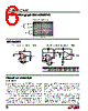
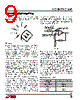
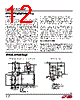
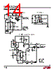
10 / 24 page  LTC1052/LTC7652 10 1052fa APPLICATIO S I FOR ATIO When all of these errors are considered, it may seem impossible to take advantage of the extremely low drift specifications of the LTC1052. To show that this is not the case, examine the temperature test circuit of Figure 3. The lead lengths of the resistors connected to the amplifier’s inputs are identical. The thermal capacity and thermal resistance each input sees is balanced because of the symmetrical connection of resistors and their identical size. Thermal EMF-induced shifts are equal in phase and amplitude, thus cancellation occurs. Figure 4 shows the response of this circuit under temperature transient conditions. Metal film resistors and an 8-pin DIP socket were used. Care was taken in the construction to thermally balance the inputs to the amplifier. The units were placed in an oven and allowed to stabilize at 25°C. The recording was started and after 100 seconds the oven, preset to 125°C, was switched on. The test was first performed on an 8-pin plastic package and then was repeated for a TO-5 package plugged into the same test board. It is significant that the change in VOS, even under these severe thermal transient conditions, is quite good. As temperature stabilizes, note that the steady-state change of VOS is well within the maximum ±0.05µV/°C drift specification. Very slight air currents can still affect even this arrangement. Figure 5 shows strip charts of output noise both with the circuit covered and with no cover in “still” air. This data illustrates why it is often prudent to enclose the LTC1052 and its attendant components inside some form of thermal baffle. Figure 3. Offset Drift Test Circuit Figure 4. Transient Response of Offset Drift Test Circuit with 100°C Temperature Step 0 MIN 25 MIN 20 MIN 5 MIN 10 0 0 10 OVEN SWITCHED ON (25°C) OVEN STABILIZED AT 12 MIN 100 SECONDS/IN 25°C TO 125°C PLASTIC 25°C TO 125°C METAL CAN ±0.05µV/°C ±0.05µV/°C 0.1µF 0.1µF 50k 3 2 7 6 8 4 1 VOS • 1000 5V LTC1052/7652 • AI04 100Ω 50k –5V 0.1µF – LTC1052 + |
|
|
リンク URL |
| ALLDATASHEETはお客様のビジネスに役立ちますか? [ DONATE ] |
Alldatasheetは | 広告 | お問い合わせ | プライバシーポリシー | データシートへのリンク | リンク交換 | メーカーリスト All Rights Reserved©Alldatasheet.com |
| Russian : Alldatasheetru.com | Korean : Alldatasheet.co.kr | Spanish : Alldatasheet.es | French : Alldatasheet.fr | Italian : Alldatasheetit.com Portuguese : Alldatasheetpt.com | Polish : Alldatasheet.pl | Vietnamese : Alldatasheet.vn Indian : Alldatasheet.in | Mexican : Alldatasheet.com.mx | British : Alldatasheet.co.uk | New Zealand : Alldatasheet.co.nz |
|
Family Site : ic2ic.com |
icmetro.com |
 Japanese ▼
 English
 Chinese
 German
 Japanese
 Russian
 Korean
 Spanish
 French
 Italian
 Portuguese
 Polish
 Vietnamese
 Indian
 Mexican
 British
 New Zealand