|
データシートサーチシステム |
|
|
データシートサーチシステム |
|
CLC420 データシート(PDF) 7 Page - National Semiconductor (TI) |
|
|
|
|||||||||||||||||||||||||||||
CLC420 データシート(HTML) 7 Page - National Semiconductor (TI) |
|
|
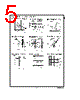
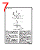
7 / 10 page  Application Division Description The CLC420 is a high-speed, slew-boosted, voltage feed- back amplifier with unity-gain stability. These features along with matched inputs, low input bias and noise currents, and excellent CMRR render the CLC420 very attractive for active filters, differential amplifiers, log amplifiers, and transimped- ance amplifiers. DC accuracy Unlike current-feedback amplifiers, voltage-feedback ampli- fiers have matched inputs. This means that the non-inverting and inverting input bias current are well matched and track over temperature, etc. As a result, by matching the resis- tance looking out of the two inputs, these errors can be re- duced to a small offset current term. Gain bandwidth product Since the CLC420 is a voltage-feedback op-amp, closed-loop bandwidth is approximately equal to the gain-bandwidth product (typically 100MHz) divided by the noise gain of the circuit (for noise gains greater than 5). At lower noise gains, higher-order amplifier poles contribute to higher closed-loop bandwidth. At low gains use the fre- quency response performance plots given in the data sheet. Another point to remember is that the closed-loop bandwidth is determined by the noise gain, not the signal gain of the cir- cuit. Noise gain is the reciprocal of the attenuation in the feedback network enclosing the op amp. For example, a CLC420 setup as a non-inverting amplifier with a closed-loop gain of +1 (a noise gain of 1) has a 300MHz bandwidth. When used as an inverting amplifier with a gain of −1 (a noise gain of 2), the bandwidth is less, typically only 100MHz. Full-power bandwidth, and slew-rate The CLC420 combines exceptional full-power bandwidths (40MHz, V 0=5Vpp, A v=+1) and slew rates (1100V/µs, A v=+1) with low (40mW) power consumption. These attrac- tive results are achieved by using slew-boosting circuitry to keep the slew rates high while consuming very little power. In non-slew boosted amplifiers, full-power bandwidth can be easily determined from slew-rate measurements, but in slew-boosting amplifiers, such as the CLC420, you can’t. For this reason we provide data for both. Slew rate is also different for inverting and non-inverting con- figurations. This occurs because common-mode signal volt- ages are present in non-inverting circuits but absent in in- verting circuits. Once again data is provided for both. DS012752-16 FIGURE 1. Recommended Non-Inverting Gain Circuit DS012752-17 FIGURE 2. Recommended Inverting Gain Circuit www.national.com 7 |
|
|
リンク URL |
| ALLDATASHEETはお客様のビジネスに役立ちますか? [ DONATE ] |
Alldatasheetは | 広告 | お問い合わせ | プライバシーポリシー | データシートへのリンク | リンク交換 | メーカーリスト All Rights Reserved©Alldatasheet.com |
| Russian : Alldatasheetru.com | Korean : Alldatasheet.co.kr | Spanish : Alldatasheet.es | French : Alldatasheet.fr | Italian : Alldatasheetit.com Portuguese : Alldatasheetpt.com | Polish : Alldatasheet.pl | Vietnamese : Alldatasheet.vn Indian : Alldatasheet.in | Mexican : Alldatasheet.com.mx | British : Alldatasheet.co.uk | New Zealand : Alldatasheet.co.nz |
|
Family Site : ic2ic.com |
icmetro.com |
 Japanese ▼
 English
 Chinese
 German
 Japanese
 Russian
 Korean
 Spanish
 French
 Italian
 Portuguese
 Polish
 Vietnamese
 Indian
 Mexican
 British
 New Zealand