|
データシートサーチシステム |
|
|
データシートサーチシステム |
|
2SP0115T2A0-CM300DX-24S データシート(PDF) 5 Page - Power Integrations, Inc. |
|
|
|||||||||||||||||||||||||||||
2SP0115T2A0-CM300DX-24S データシート(HTML) 5 Page - Power Integrations, Inc. |
|
|
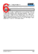
5 / 8 page  SCALE™-2 2SP0115T2A0(C)-CM300DX-24S Data Sheet www.power.com/gate-driver Page 5 Footnotes to the Key Data 1) The gate current is limited by the gate resistors located on the driver. 2) If the specified value is exceeded, this indicates a driver overload. It should be noted that the driver is not protected against overload. 3) If the specified value is exceeded, this indicates a driver overload. It should be noted that the driver is not protected against overload. From 70°C to 85°C, the maximum permissible output power can be linearly interpolated from the given data. 4) This limit is due to active clamping. Refer to the “Description & Application Manual for 2SP0115T SCALE-2 IGBT Drivers”. 5) Undervoltage monitoring of the primary-side supply voltage (VCC to GND). If the voltage drops below this limit, a fault is transmitted to the corresponding outputs and the IGBTs are switched off. 6) Undervoltage monitoring of the secondary-side supply voltage (Visox to Veex and Veex to COMx which correspond with the approximate turn-on and turn-off gate-emitter voltages). If the corresponding voltage drops below this limit, the IGBT is switched off and a fault is transmitted to the corresponding output. 7) The input impedance can be modified to values <18 kΩ (customer-specific solution). 8) Turn-on and turn-off threshold values can be increased (customer-specific solution). 9) The resulting pulse width of the direct output of the gate drive unit for short-circuit type I (excluding the delay of the gate resistors) is the sum of response time plus delay to IGBT turn-off. 10) The turn-off event of the IGBT is delayed by the specified time after the response time. 11) Factory set value. The blocking time can be reduced with an external resistor. Refer to the “Description & Application Manual for 2SP0115T SCALE-2 IGBT Drivers”. 12) Measured from the transition of the turn-on or turn-off command at the driver input to direct output of the gate drive unit (excluding the delay of the gate resistors). 13) Output rise and fall times are measured between 10% and 90% of the nominal output swing with an output load of 10Ω and 40nF. The values are given for the driver side of the gate resistors. The time constant of the output load in conjunction with the present gate resistors leads to an additional delay at the load side of the gate resistors. 14) Transmission delay of the fault state from the secondary side to the primary status outputs. 15) The gate resistors can be leaded or surface mounted. Power Integrations reserves the right to determine which type will be used. Typically, higher quantities will be produced with SMD resistors and small quantities with leaded resistors. 16) HiPot testing (= dielectric testing) must generally be restricted to suitable components. This gate driver is suited for HiPot testing. Nevertheless, it is strongly recommended to limit the testing time to 1s slots as stipulated by EN 50178. Excessive HiPot testing at voltages much higher than 850VAC(eff) may lead to insulation degradation. No degradation has been observed over 1min. testing at 3800VAC(eff). The transformer of every production sample shipped to customers has undergone 100% testing at the given value or higher (< 5100VAC(eff)) for 1s. 17) Partial discharge measurement is performed in accordance with IEC 60270 and isolation coordination specified in EN 50178. The partial discharge extinction voltage between primary and either secondary side is coordinated for safe isolation to EN 50178. 18) Jitter measurements are performed with input signals INx switching between 0V and 15V referred to GND, with a corresponding rise time and fall time of 8ns. 19) Note that the dead time may vary from sample to sample. A tolerance of approximately ±20% may be expected. If higher timing precisions are required, Power Integrations recommends using direct mode and generating the dead time externally. 20) A version with extended operating temperature range of –40°C…85°C (2SP0115T2B0) can also be supplied. 21) The storage temperature inside the original package (1) or in case the coating material of coated products may touch external parts (2) must be limited to the given value. Otherwise, it is limited to 90°C. 22) The component surface temperature, which may strongly vary depending on the operating condition, must be limited to the given value for coated driver versions to ensure long-term reliability of the coating material. |
|
|
リンク URL |
| ALLDATASHEETはお客様のビジネスに役立ちますか? [ DONATE ] |
Alldatasheetは | 広告 | お問い合わせ | プライバシーポリシー | データシートへのリンク | リンク交換 | メーカーリスト All Rights Reserved©Alldatasheet.com |
| Russian : Alldatasheetru.com | Korean : Alldatasheet.co.kr | Spanish : Alldatasheet.es | French : Alldatasheet.fr | Italian : Alldatasheetit.com Portuguese : Alldatasheetpt.com | Polish : Alldatasheet.pl | Vietnamese : Alldatasheet.vn Indian : Alldatasheet.in | Mexican : Alldatasheet.com.mx | British : Alldatasheet.co.uk | New Zealand : Alldatasheet.co.nz |
|
Family Site : ic2ic.com |
icmetro.com |
 Japanese ▼
 English
 Chinese
 German
 Japanese
 Russian
 Korean
 Spanish
 French
 Italian
 Portuguese
 Polish
 Vietnamese
 Indian
 Mexican
 British
 New Zealand