|
データシートサーチシステム |
|
|
データシートサーチシステム |
|
E5CC-RX2ABM-000 データシート(PDF) 27 Page - Omron Electronics LLC |
|
|
|||||||||||||||||||||||||||||
E5CC-RX2ABM-000 データシート(HTML) 27 Page - Omron Electronics LLC |
|
|
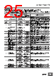
27 / 138 page  E5CC/E5CC-B/E5CC-U 27 Characteristics *1. The indication accuracy of K thermocouples in the -200 to 1,300°C range, T and N thermocouples at a temperature of -100°C max., and U and L thermocouples at any temperatures is ±2°C ±1 digit max. The indication accuracy of the B thermocouple at a temperature of 400°C max. is not specified. The indication accuracy of B thermocouples at a temperature of 400 to 800°C is ±3°C max. The indication accuracy of the R and S thermocouples at a temperature of 200°C max. is ±3°C ±1 digit max. The indication accuracy of C/W thermocouples is (±0.3% of PV or ±3°C, whichever is greater) ±1 digit max. The indication accuracy of PL II thermocouples is (±0.3% of PV or ±2°C, whichever is greater) ±1 digit max. *2. However, the precision between 0 and 4 mA for a 0 to 20 mA output is ±1% FS max. *3. Ambient temperature: -10°C to 23°C to 55°C, Voltage range: -15% to 10% of rated voltage *4. K thermocouple at -100°C max.: ±10°C max. *5. The unit is determined by the setting of the Integral/Derivative Time Unit parameter. *6. External communications (RS-485) and USB-serial conversion cable communications can be used at the same time. *7. CX-Thermo version 4.67 or higher is required for the E5CC-B linear current output type. Indication accuracy (at the ambient temperature of 23°C) E5CC/E5CC-B Thermocouple: ( ±0.3% of indication value or ±1°C, whichever is greater) ±1 digit max. *1 Platinum resistance thermometer: ( ±0.2% of indication value or ±0.8°C, whichever is greater) ±1 digit max. Analog input: ±0.2% FS ±1 digit max. CT input: ±5% FS ±1 digit max. E5CC-U Thermocouple: ( ±1% of indication value or ±2°C, whichever is greater) ±1 digit max. *1 Platinum resistance thermometer: ( ±0.2% of indication value or ±0.8°C, whichever is greater) ±1 digit max. Analog input: ±0.2% FS ±1 digit max. Transfer output accuracy ±0.3% FS max. Simple transfer output accuracy ±0.3% FS max.*2 Remote SP Input Type ±0.2% FS ±1 digit max. Influence of temperature *3 Thermocouple input (R, S, B, C/W, PL II): ( ±1% of indication value or ±10°C, whichever is greater) ±1 digit max. Other thermocouple input: ( ±1% of indication value or ±4°C, whichever is greater) ±1 digit max. *4 Platinum resistance thermometer: ( ±1% of indication value or ±2°C, whichever is greater) ±1 digit max. Analog input: ±1%FS ±1 digit max. CT input: ±5% FS ±1 digit max. Remote SP input: ±1% FS ±1 digit max. Influence of voltage *3 Influence of EMS. (at EN 61326-1) Input sampling period 50 ms Hysteresis Temperature input: 0.1 to 999.9°C or °F (in units of 0.1°C or °F) Analog input: 0.01% to 99.99% FS (in units of 0.01% FS) Proportional band (P) Temperature input: 0.1 to 999.9°C or °F (in units of 0.1°C or °F) Analog input: 0.1% to 999.9% FS (in units of 0.1% FS) Integral time (I) 0 to 9999 s (in units of 1 s), 0.0 to 999.9 s (in units of 0.1 s) *5 Derivative time (D) 0 to 9999 s (in units of 1 s), 0.0 to 999.9 s (in units of 0.1 s) *5 Proportional band (P) for cooling Temperature input: 0.1 to 999.9°C or °F (in units of 0.1°C or °F) Analog input: 0.1% to 999.9% FS (in units of 0.1% FS) Integral time (I) for cooling 0 to 9999 s (in units of 1 s), 0.0 to 999.9 s (in units of 0.1 s) *5 Derivative time (D) for cooling 0 to 9999 s (in units of 1 s), 0.0 to 999.9 s (in units of 0.1 s) *5 Control period 0.1, 0.2, 0.5, 1 to 99 s (in units of 1 s) Manual reset value 0.0 to 100.0% (in units of 0.1%) Alarm setting range -1999 to 9999 (decimal point position depends on input type) Influence of signal source resistance Thermocouple: 0.1°C/Ω max. (100 Ωmax.) Platinum resistance thermometer: 0.1°C/ Ω max. (10 Ω max.) Insulation resistance 20 M Ω min. (at 500 VDC) Dielectric strength 3,000 VAC, 50/60 Hz for 1 min between terminals of different charge Vibration Malfunction 10 to 55 Hz, 20 m/s2 for 10 min each in X, Y, and Z directions Resistance 10 to 55 Hz, 20 m/s2 for 2 hrs each in X, Y, and Z directions Shock Malfunction 100 m/s2, 3 times each in X, Y, and Z directions Resistance 300 m/s2, 3 times each in X, Y, and Z directions Weight E5CC/E5CC-B: Controller: Approx. 120 g, Mounting Adapter: Approx. 10 g E5CC-U: Controller: Approx. 100 g, Mounting Adapter: Approx. 10 g Degree of protection E5CC/E5CC-B: Front panel: IP66, Rear case: IP20, Terminals: IP00 E5CC-U: Front panel: IP50, Rear case: IP20, Terminals: IP00 Memory protection Non-volatile memory (number of writes: 1,000,000 times) Setup Tool E5CC: CX-Thermo version 4.5 or higher E5CC-B: CX-Thermo version 4.65 or higher *7 E5CC-U: CX-Thermo version 4.61 or higher Setup Tool port E5CC/E5CC-B/E5CC-U top panel: An E58-CIFQ2 USB-Serial Conversion Cable is used to connect to a USB port on the computer. *6 |
|
リンク URL |
| ALLDATASHEETはお客様のビジネスに役立ちますか? [ DONATE ] |
Alldatasheetは | 広告 | お問い合わせ | プライバシーポリシー | データシートへのリンク | リンク交換 | メーカーリスト All Rights Reserved©Alldatasheet.com |
| Russian : Alldatasheetru.com | Korean : Alldatasheet.co.kr | Spanish : Alldatasheet.es | French : Alldatasheet.fr | Italian : Alldatasheetit.com Portuguese : Alldatasheetpt.com | Polish : Alldatasheet.pl | Vietnamese : Alldatasheet.vn Indian : Alldatasheet.in | Mexican : Alldatasheet.com.mx | British : Alldatasheet.co.uk | New Zealand : Alldatasheet.co.nz |
|
Family Site : ic2ic.com |
icmetro.com |
 Japanese ▼
 English
 Chinese
 German
 Japanese
 Russian
 Korean
 Spanish
 French
 Italian
 Portuguese
 Polish
 Vietnamese
 Indian
 Mexican
 British
 New Zealand