Preliminary
8-131
RF2488
Rev A0 010905
8
Application Information
Calculating the mixer output match
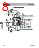
The evaluation boards mixer output match is explained below.
The match is made up of six components, each of which is discussed below.
Inductor L1
This inductor, along with capacitors C1 and C2 determine the resonant frequency of the current combining circuit, as well
as the output impedance at the resonant point. The output impedance will be dependent on the parasitic resistance of
the inductor RP. A high Q inductor will result in a high output impedance.
Inductor L2
This inductor functions as a choke at the IF frequency, and should be made as large as possible, to not interact with the
current combiner network. In addition, it provides a DC path from VCC to the mixer core transistors.
Capacitors C1 and C2
These capacitors should be equal, and along with L1, define the resonant frequency.
Capacitor C3
This capacitor is used to provide a DC-block.
Resistor R1
This is primarily used to set the output impedance of the network. The impedance at the resonant frequency can be
measured, and R1 can be placed in parallel to reduce the real impedance to the desired value. Alternatively, an approxi-
mation can be made using the following equation.
This is only an approximation, because it assumes the capacitors have infinite Q, and does not take into account PCB
parasitics.
The following equation can be used to approximately calculate the resonant frequency of the circuit.
IF+
IF-
L1
C1
C2
L2
R1
C3
IF OUT
V
CC
R
1
1
R
OUT
-------------
1
R
P
------
–
èø
æö
1
–
=
f
IF
1
2
π L1
2
------ C1
C
EQ
+
()
-----------------------------------------------
=


 Japanese ▼
 English
 Chinese
 German
 Japanese
 Russian
 Korean
 Spanish
 French
 Italian
 Portuguese
 Polish
 Vietnamese
 Indian
 Mexican
 British
 New Zealand