|
データシートサーチシステム |
|
|
データシートサーチシステム |
|
EV6000 データシート(PDF) 5 Page - CML Microcircuits |
|
|
|||||||||||||||||||||||||||||
EV6000 データシート(HTML) 5 Page - CML Microcircuits |
|
|
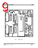
5 / 18 page  Evaluation Kit User Manual for PIC Board EV6000 © 1996 Consumer Microcircuits Limited 5 UM6000/3 1.3 Quick Start This section provides instructions for users who wish to experiment immediately with the evaluation kit. A fuller description of the kit and its use appears later in this document. 1.3.1 Setting-Up This evaluation kit comprises a single board containing a socket for a 40-pin DIL PIC (or compatible) general-purpose µC, which the user may re-program with his applications software. THE EV6000 COMES WITH A PRE-CONFIGURED PIC 16C74AJW OR EQUIVALENT, CONTAINING DIAGNOSTIC FIRMWARE AND APPLICATION SPECIFIC DEMONSTRATION FIRMWARE FOR THE EV6020 AND EV6040 EVALUATION KITS. THE EV6000 IS SET FOR OPERATION AT 5.0V. The kit also contains two 20-way flat cables (one of which is needed for connection to an EV6020 or EV6040 CML Evaluation Kit) and a 9-way D-type RS232 cable (for connection to a PC), as shown in the Block Diagram of Figure 1. No board adjustments are required by the user. BEFORE APPLYING POWER, PLEASE CHECK THE FOLLOWING: ENSURE THE PIC µµC IS PLUGGED INTO SOCKET U2 ON THE EV6000 BOARD. CONNECT THE 9-WAY RS232 CABLE BETWEEN SOCKET J3 AND THE SERIAL PORT OF A PC. FOR USE WITH EV6020 OR EV6040 EVALUATION KITS, CONNECT A 20-WAY FLAT CABLE BETWEEN SOCKETS J1 ON THE EV6000 AND EV6020 OR EV6040 BOARDS. The EV6000 board has connections for a single 8 - 35V dc power supply. Only one board (as shown in Figure 1) needs to be connected as power is supplied to the other board over the flat cable. Each board has its own power supply regulator chip, with a jumper to select 3.3V or 5.0V (default) operation. MAKE SURE BOTH BOARDS HAVE THIS JUMPER SET TO THE SAME VOLTAGE. DAMAGE MAY RESULT IF THIS STEP IS NOT OBSERVED. DO NOT OPERATE EITHER BOARD WITH ITS VOLTAGE SELECTION JUMPER REMOVED. Ensure that the component value jumpers on the EV6020 or EV6040 evaluation board are correctly set for 3.3V or 5.0V operation. Please refer to Section 1.6.1.1 for further details. Connect any other equipment as shown in Figure 1. Ensure the PC terminal emulator program is set up as detailed in section 1.2.1.2. 1.3.2 Operation The EV6000 kit is designed to control the operation of an EV6020 or EV6040 Evaluation Kit. The firmware which is pre-configured into the PIC µC has both diagnostic and application specific commands. Refer to section 1.6.2.2 for the diagnostics and section 1.6.2.3 for the applications. The PICPROGA.EXE program can be used to re-program the PIC µC firmware, if required. |
|
|
リンク URL |
| ALLDATASHEETはお客様のビジネスに役立ちますか? [ DONATE ] |
Alldatasheetは | 広告 | お問い合わせ | プライバシーポリシー | データシートへのリンク | リンク交換 | メーカーリスト All Rights Reserved©Alldatasheet.com |
| Russian : Alldatasheetru.com | Korean : Alldatasheet.co.kr | Spanish : Alldatasheet.es | French : Alldatasheet.fr | Italian : Alldatasheetit.com Portuguese : Alldatasheetpt.com | Polish : Alldatasheet.pl | Vietnamese : Alldatasheet.vn Indian : Alldatasheet.in | Mexican : Alldatasheet.com.mx | British : Alldatasheet.co.uk | New Zealand : Alldatasheet.co.nz |
|
Family Site : ic2ic.com |
icmetro.com |
 Japanese ▼
 English
 Chinese
 German
 Japanese
 Russian
 Korean
 Spanish
 French
 Italian
 Portuguese
 Polish
 Vietnamese
 Indian
 Mexican
 British
 New Zealand