|
データシートサーチシステム |
|
|
データシートサーチシステム |
|
AD7912AUJ-R2 データシート(PDF) 20 Page - Analog Devices |
|
|
|||||||||||||||||||||||||||||
AD7912AUJ-R2 データシート(HTML) 20 Page - Analog Devices |
|
|
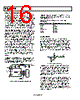
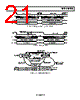
20 / 32 page  AD7912/AD7922 Rev. 0 | Page 20 of 32 POWER-UP TIME The power-up time of the AD7912/AD7922 is 1 µs, which means that with any frequency of SCLK up to 18 MHz, one dummy cycle is always sufficient to allow the device to power up. Once the dummy cycle is complete, the ADC is fully powered up and the input signal is fully acquired. The quiet time, tQUIET, must still be allowed from the point at which the bus goes back into three-state after the dummy conversion to the next falling edge of CS. When running at a 1 MSPS throughput rate, the AD7912/AD7922 power up and acquire a signal within ±1 LSB in one dummy cycle, that is, 1 µs. When powering up from power-down mode with a dummy cycle, as in Figure 29, the track-and-hold that was in hold mode while the part was powered down returns to track mode on the fifth SCLK falling edge that the part receives after the falling edge of CS. This is shown as point A in Figure 29. At this point, the part starts to acquire the signal on the channel selected in the current dummy conversion. Although at any SCLK frequency one dummy cycle is sufficient to power up the device and acquire VIN, it does not necessarily mean that a full dummy cycle of 16 SCLKs must always elapse to power up the device and acquire VIN fully. 1 µs is sufficient to power up the device and acquire the input signal. For example, if a 5 MHz SCLK frequency was applied to the ADC, the cycle time would be 3.2 µs. In one dummy cycle, 3.2 µs, the part would be powered up and VIN acquired fully. However, after 1 µs with a 5 MHz SCLK, only five SCLK cycles would have elapsed. At this stage, the ADC would be fully powered up and the signal is acquired. Therefore, in this case, CS can be brought high after the 10th SCLK falling edge. If CS is brought high anytime after the 13th SCLK falling edge, the part enters normal mode for the next conversion. CS has to be brought low again after a time, tQUIET, to initiate the conversion. However, if CS is brought high anytime after the 10th and before the 12th SCLK falling edge, the part enters daisy-chain mode. When power supplies are first applied to the AD7912/AD7922, the ADC can power up in either power-down mode, normal mode, or daisy-chain mode. Because of this, it is best to allow a dummy cycle to elapse to ensure that the part is fully powered up before attempting a valid conversion. Likewise, if the user wants to keep the part in power-down mode while not in use and to power up in power-down mode, then the dummy cycle can be used to ensure that the device is in power-down mode by executing a cycle such as that shown in Figure 28. Once supplies are applied to the AD7912/AD7922, the power- up time is the same as when powering up from the power-down mode. It takes the part approximately 1 µs to power up fully in normal mode. It is not necessary to wait 1 µs before executing a dummy cycle to ensure the desired mode of operation. Instead, the dummy cycle can occur directly after power is supplied to the ADC. If the first valid conversion is then performed directly after the dummy conversion, care must be taken to ensure that adequate acquisition time has been allowed. When the ADC powers up initially after supplies are applied, the track-and-hold is in hold. It returns to track on the fifth SCLK falling edge that the part receives after the falling edge of CS. DAISY-CHAIN MODE When the ADC is in this mode of operation, the part operates as a shift register. This mode is intended for applications where more than one ADC is used, connected in a daisy-chain configuration (see Figure 33). All ADCs are addressed by the same CS signal and the same serial clock. The conversion result stored in the internal shift register in each ADC is shifted from one device to the following in the chain. See the Daisy-Chain Example in the following section for more details. To enter daisy-chain mode, the conversion process must be interrupted by bringing CS high after the 10th falling edge of SCLK and before the 12th falling edge of SCLK, as shown in Figure 27. To ensure that the AD7912/AD7922 are placed into daisy-chain mode, CS should not be brought high until at least 20 ns after the 10th SCLK falling edge and before the 12th SCLK falling edge. Once CS has been brought high in this window of SCLKs, the part enters daisy-chain mode, the conversion that was initiated by the falling edge of CS is terminated, and DOUT goes back into three-state. If CS is brought high between the 10th and the 12th SCLK falling edge, the part enters daisy-chain mode and the data shifted from one ADC to the next one in the chain is valid data (see Figure 34 and Figure 35). If CS is brought high between the 12th and the 13th SCLK falling edge, the part enters daisy-chain mode, but the data shifted in the chain is invalid data. To keep the part in daisy-chain mode, the CHN and STY bits in the DIN word must be inverted relative to each other in each 16 SCLKs cycle. A conversion with the CHN and STY bits set to the same value in the DIN word while the device is in daisy- chain mode forces the part to go back into normal mode in the next cycle, as shown in Figure 30. To exit this mode of operation, the user can perform a dummy cycle or can set the STY bit to the CHN bit value on the DIN word during a conversion cycle. When performing a dummy conversion to exit this mode, CS must be brought high anytime after the 10th SCLK falling edge and before the 13th SCLK falling edge, as shown in Figure 31. The device enters normal mode, and valid data from the channel selected in the dummy cycle results in the next conversion. Figure 32 summarizes the modes of operation, how to change between modes, the values for the bits in the DIN and DOUT words in different modes, and in the transitions between modes. |
|
リンク URL |
| ALLDATASHEETはお客様のビジネスに役立ちますか? [ DONATE ] |
Alldatasheetは | 広告 | お問い合わせ | プライバシーポリシー | データシートへのリンク | リンク交換 | メーカーリスト All Rights Reserved©Alldatasheet.com |
| Russian : Alldatasheetru.com | Korean : Alldatasheet.co.kr | Spanish : Alldatasheet.es | French : Alldatasheet.fr | Italian : Alldatasheetit.com Portuguese : Alldatasheetpt.com | Polish : Alldatasheet.pl | Vietnamese : Alldatasheet.vn Indian : Alldatasheet.in | Mexican : Alldatasheet.com.mx | British : Alldatasheet.co.uk | New Zealand : Alldatasheet.co.nz |
|
Family Site : ic2ic.com |
icmetro.com |
 Japanese ▼
 English
 Chinese
 German
 Japanese
 Russian
 Korean
 Spanish
 French
 Italian
 Portuguese
 Polish
 Vietnamese
 Indian
 Mexican
 British
 New Zealand