|
データシートサーチシステム |
|
|
データシートサーチシステム |
|
AD7912AUJ-R2 データシート(PDF) 22 Page - Analog Devices |
|
|
|||||||||||||||||||||||||||||
AD7912AUJ-R2 データシート(HTML) 22 Page - Analog Devices |
|
|
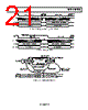
22 / 32 page  AD7912/AD7922 Rev. 0 | Page 22 of 32 DAISY-CHAIN EXAMPLE In applications where fast throughput is not critical, connecting several ADCs in a daisy chain lets the user perform simultane- ous sampling on all the ADCs contained in the chain using the minimum number of I/O lines from the µC/DSP ports. The user needs to alternate modes of operation in the ADCs. While the parts are in normal mode, the conversion is per- formed and the result from each ADC is stored in its internal register. Following the conversion, the parts are placed into daisy-chain mode and the user can proceed to read the result from each ADC by shifting the data from one ADC to the next. For clarity in the following example, only two devices are connected in a daisy chain. Both AD7912/AD7922 are addressed by the same CS and SCLK signal. The devices are configured as shown in Figure 33 for simultaneous conversion and shifting read operation later. The output of the device on the left, ADC1, feeds the input of the device on the right, ADC2. During a normal conversion, the conversion result is stored internally and output to the DOUT pin. In daisy-chain mode, the value internally stored is output through the DOUT pin and the information provided at the DIN pin is shifted into the internal register. When several AD7912/AD7922 are connected in a daisy chain, the sequence is as follows: 1. Normal conversion. Every AD7912/AD7922 performs a conversion on its selected channel and the result is stored in the internal shift register. 2. Entering daisy-chain mode. In this cycle, CS is brought high between the 10th and 12th SCLK falling edges and all the devices enter daisy- chain mode. 3. Daisy-chain cycles. While the AD7912/AD7922 are in daisy-chain mode, the conversion results from all the devices in the chain are read, and the parts are configured for the next conversion. The user needs to perform as many read cycles as there are devices in the chain. To keep all the AD7912/AD7922 in daisy-chain mode, the CHN and STY bits in the DIN input must always be inverted. Data is shifted through the devices in the chain. Data is clocked into the device in the chain by the same clock used to clock data out. The first word clocked into the DIN pin once the devices are in daisy-chain mode is eventually lost. The second word clocked into the DIN pin contains the channel configura- tion data for the last device in the chain, the third word clocked into the DIN pin contains the channel configura- tion data for the second last device in the chain, and so on. Then the selected channel for the first device in the chain is clocked in the cycle executed after all the data has been read, that is, in the short cycle used to change modes of operation. See Figure 34. 4. Enter normal mode. After reading the conversion results from the AD7912/ AD7922, the devices need to be placed into normal mode to perform a new conversion. Therefore, in this cycle CS is brought high between the 10th and the 13th SCLK falling edge. The DOUT line contains invalid data and DIN contains the selected channel for the first device in the chain. The remaining devices in the chain have already set the channel for the next conversion as a result of the data shifted in during daisy-chain mode. 5. Normal conversion. A new conversion can be performed on the newly selected channels. The process can be repeated by following the previous steps. Figure 34 shows the timing diagram for two AD7912/ AD7922 connected in a daisy chain, as shown in Figure 33. The DIN signal corresponds to the DIN pin on the first AD7912/AD7922 in the chain, and the DOUT signal corresponds to the DOUT pin on the last AD7912/AD7922 in the chain. The words clocked into the DIN pin, which set up the channel for the next conversion for the two AD7912/AD7922, are shown as COMMAND1 and COMMAND2. The first word clocked in, COMMAND3, does not remain in any of the ADCs in the chain and is eventually lost. The channel configuration data for the first device in the chain, COMMAND1, is clocked in while changing from daisy-chain mode to normal mode. Figure 35 is a more detailed diagram that shows the data presented on the DIN pin and clocked out on the DOUT pin for each of the AD7912/AD7922 in Figure 33. If the DOUT1 (or DIN2) signal is ignored, Figure 35 brings about Figure 34. SCLK DIN1 DOUT1 ADC1 CS SCLK CS SCLK DIN2 DOUT2 ADC2 CS DIN DOUT FSX SCLK TX DR µC/DSP Figure 33. AD7912/AD7922 Connected in Daisy Chain |
|
リンク URL |
| ALLDATASHEETはお客様のビジネスに役立ちますか? [ DONATE ] |
Alldatasheetは | 広告 | お問い合わせ | プライバシーポリシー | データシートへのリンク | リンク交換 | メーカーリスト All Rights Reserved©Alldatasheet.com |
| Russian : Alldatasheetru.com | Korean : Alldatasheet.co.kr | Spanish : Alldatasheet.es | French : Alldatasheet.fr | Italian : Alldatasheetit.com Portuguese : Alldatasheetpt.com | Polish : Alldatasheet.pl | Vietnamese : Alldatasheet.vn Indian : Alldatasheet.in | Mexican : Alldatasheet.com.mx | British : Alldatasheet.co.uk | New Zealand : Alldatasheet.co.nz |
|
Family Site : ic2ic.com |
icmetro.com |
 Japanese ▼
 English
 Chinese
 German
 Japanese
 Russian
 Korean
 Spanish
 French
 Italian
 Portuguese
 Polish
 Vietnamese
 Indian
 Mexican
 British
 New Zealand