|
データシートサーチシステム |
|
|
データシートサーチシステム |
|
WM8196 データシート(PDF) 27 Page - Cirrus Logic |
|
|
|||||||||||||||||||||||||||||
WM8196 データシート(HTML) 27 Page - Cirrus Logic |
|
|
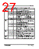
27 / 32 page  WM8196 Production Data w PD Rev 4.6 October 2008 27 REGISTER MAP DESCRIPTION The following table describes the function of each of the control bits shown in Table 6. REGISTER BIT NO BIT NAME(S) DEFAULT DESCRIPTION 0 EN 1 When SELPD = 1 this bit has no effect. When SELPD = 0 this bit controls the global power down: 0 = complete power down, 1 = fully active. 1 CDS 1 Select correlated double sampling mode: 0 = single ended mode, 1 = CDS mode. 2 MONO 0 Mono/colour select: 0 = colour, 1 = monochrome operation. 3 SELPD 0 Selective power down: 0 = no individual control, 1 = individual blocks can be disabled (controlled by SELDIS[3:0]). Offsets PGA output to optimise the ADC range for different polarity sensor output signals. Zero differential PGA input signal gives: 5:4 PGAFS[1:0] 00 00 = Zero output (use for bipolar video) 01 = Zero output 10 = Full-scale positive output (use for negative going video) 11 = Full-scale negative output (use for positive going video) 6 MODE4 0 Required when operating in MODE4: 0 = other modes, 1 = MODE4. Setup Register 1 7 Reserved 0 Must be set to zero Determines the output data format. 1:0 MUXOP[1:0] 00 00 = 16-bit parallel 01 = 8-bit multiplexed (8+8 bits) 10 = 8-bit multiplexed mode (8+8 bits) 11 = 4-bit multiplexed mode (4+4+4+4 bits) 2 INVOP 0 Digitally inverts the polarity of output data. 0 = negative going video gives negative going output, 1 = negative-going video gives positive going output data. 3 VRLCEXT 0 When set powers down the RLCDAC, changing its output to Hi-Z, allowing VRLC/VBIAS to be externally driven. 5 RLCDACRNG 1 Sets the output range of the RLCDAC. 0 = RLCDAC ranges from 0 to AVDD (approximately), 1 = RLCDAC ranges from 0 to VRT (approximately). Sets the output latency in ADC clock periods. 1 ADC clock period = 2 MCLK periods except in Mode 3 where 1 ADC clock period = 3 MCLK periods. Setup Register 2 7:6 DEL[1:0] 00 00 = Minimum latency 01 = Delay by one ADC clock period 10 = Delay by two ADC clock periods 11 = Delay by three ADC clock periods 3:0 RLCV[3:0] 1111 Controls RLCDAC driving VRLC pin to define single ended signal reference voltage or Reset Level Clamp voltage. See Electrical Characteristics section for ranges. CDS mode reset timing adjust. 5:4 CDSREF[1:0] 01 00 = Advance 1 MCLK period 01 = Normal 10 = Retard 1 MCLK period 11 = Retard 2 MCLK periods Monochrome mode channel select. Setup Register 3 7:6 CHAN[1:0] 00 00 = Red channel select 01 = Green channel select 10 = Blue channel select 11 = Reserved Software Reset Any write to Software Reset causes all cells to be reset. It is recommended that a software reset be performed after a power-up before any other register writes. Auto-cycle Reset Any write to Auto-cycle Reset causes the auto-cycle counter to reset to RINP. This function is only required when LINEBYLINE = 1. |
|
リンク URL |
| ALLDATASHEETはお客様のビジネスに役立ちますか? [ DONATE ] |
Alldatasheetは | 広告 | お問い合わせ | プライバシーポリシー | データシートへのリンク | リンク交換 | メーカーリスト All Rights Reserved©Alldatasheet.com |
| Russian : Alldatasheetru.com | Korean : Alldatasheet.co.kr | Spanish : Alldatasheet.es | French : Alldatasheet.fr | Italian : Alldatasheetit.com Portuguese : Alldatasheetpt.com | Polish : Alldatasheet.pl | Vietnamese : Alldatasheet.vn Indian : Alldatasheet.in | Mexican : Alldatasheet.com.mx | British : Alldatasheet.co.uk | New Zealand : Alldatasheet.co.nz |
|
Family Site : ic2ic.com |
icmetro.com |
 Japanese ▼
 English
 Chinese
 German
 Japanese
 Russian
 Korean
 Spanish
 French
 Italian
 Portuguese
 Polish
 Vietnamese
 Indian
 Mexican
 British
 New Zealand