|
データシートサーチシステム |
|
|
データシートサーチシステム |
|
EMC1002 データシート(PDF) 18 Page - SMSC Corporation |
|
|
|||||||||||||||||||||||||||||
EMC1002 データシート(HTML) 18 Page - SMSC Corporation |
|
|
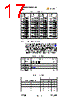
18 / 22 page  1°C Dual SMBus Sensor with Resistance Error Correction Datasheet Revision 1.3 (03-24-06) 18 SMSC EMC1002 DATASHEET Chapter 5 Application Information This chapter provides information on maintaining accuracy when using diodes as remote sensors with SMSC Environmental Monitoring and Control devices. It is assumed that the users have some familiarity with hardware design and transistor characteristics. SMSC supplies a family Environmental Monitoring and Control (EMC) devices that are capable of accurately measuring temperatures. Most devices include an internal temperature sensor along with the ability to measure one or more external sensors. The characteristics of an appropriate diode for use as the external sensor are listed in this chapter. Recommendations for the printed circuit board layout are provided to help reduce error caused by electrical noise or trace resistance. 5.1 Maintaining Accuracy 5.1.1 Physical Factors Temperature measurement is performed by measuring the change in forward bias voltage of a diode when different currents are forced through the junction. The circuit board itself can impact the ability to accurately measure these small changes in voltage. 5.1.1.1 Layout Apply the following guidelines when designing the printed circuit board: 1. Route the remote diode traces on the top layer. 2. Place a ground guard signal on both sides of the differential pair. This guard band should be connected to the ground plane at least every 0.25 inches. 3. Place a ground plane on the layer immediately below the diode traces. 4. Keep the diode traces as short as possible. 5. Keep the diode traces parallel, and the length of the two traces identical within 0.3 inches. 6. Use a trace width of 0.01 inches with a 0.01 inch guard band on each side. 7. Keep the diode traces away from sources of high frequency noise such as power supply filtering or high speed digital signals. 8. When the diode traces must cross high speed digital signals, make them cross at a 90 degree angle. 9. Avoid joints of copper to solder that can introduce thermocouple effects. These recommendations are illustrated in Figure 5.1 Routing the Diode Traces on page 18. Figure 5.1 Routing the Diode Traces COPPER TRACE COPPER TRACE .01 WIDE MIN. .01 GAP MIN. .01 WIDE MIN. GND PLANE .01 GAP MIN. GND PLANE .01 GAP MIN. COPPER PLANE (TO SHIELD FROM NOISE) BOARD MATERIAL RECOMMEND VIA STICTCHING AT .25 INCH INTERVALS. DP or DN DP or DN |
|
|
リンク URL |
| ALLDATASHEETはお客様のビジネスに役立ちますか? [ DONATE ] |
Alldatasheetは | 広告 | お問い合わせ | プライバシーポリシー | データシートへのリンク | リンク交換 | メーカーリスト All Rights Reserved©Alldatasheet.com |
| Russian : Alldatasheetru.com | Korean : Alldatasheet.co.kr | Spanish : Alldatasheet.es | French : Alldatasheet.fr | Italian : Alldatasheetit.com Portuguese : Alldatasheetpt.com | Polish : Alldatasheet.pl | Vietnamese : Alldatasheet.vn Indian : Alldatasheet.in | Mexican : Alldatasheet.com.mx | British : Alldatasheet.co.uk | New Zealand : Alldatasheet.co.nz |
|
Family Site : ic2ic.com |
icmetro.com |
 Japanese ▼
 English
 Chinese
 German
 Japanese
 Russian
 Korean
 Spanish
 French
 Italian
 Portuguese
 Polish
 Vietnamese
 Indian
 Mexican
 British
 New Zealand