|
データシートサーチシステム |
|
|
データシートサーチシステム |
|
EMC1002 データシート(PDF) 19 Page - SMSC Corporation |
|
|
|||||||||||||||||||||||||||||
EMC1002 データシート(HTML) 19 Page - SMSC Corporation |
|
|
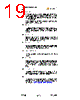
19 / 22 page  1°C Dual SMBus Sensor with Resistance Error Correction Datasheet SMSC EMC1002 19 Revision 1.3 (03-24-06) DATASHEET 5.1.1.2 Bypass Capacitors Accurate temperature measurements require a clean, stable power supply. Locate a 0.1µF capacitor as close as possible to the power pin with a good ground. A low ESR capacitor (such as a 10µF ceramic) should be placed across the power source. Add additional power supply filtering in systems that have a noisy power supply. A capacitor may be placed across the DP/DN pair at the remote sensor in noisy environments. Do not exceed a value of 2.2nF if this capacitor is installed. 5.1.1.3 Manufacturing Circuit board assembly processes may leave a residue on the board. This residue can result in unexpected leakage currents that may introduce errors if the circuit board is not clean. For example, processes that use water-soluble soldering fluxes have been known to cause problems if the board is not kept clean. 5.1.1.4 Thermal Considerations Keep the sensor in good thermal contact with the component to be measured. The temperature of the leads of a discrete diode will greatly impact the temperature of the diode junction. Make use of the printed circuit board to disperse any self-heating that may occur. 5.1.1.5 Remote Sensors Connected by Cables When connecting remote diodes with a cable (instead of traces on the PCB) use shielded twisted pair cable. The shield should be attached to ground near the EMC1002, and should be left unconnected at the sensor end. Belden 8451 cable is a good choice for this application. 5.1.2 Sensor Characteristics The characteristics of the diode junction used for temperature sensing will affect the accuracy of the measurement. 5.1.2.1 Selecting a Sensor A diode connected small signal transistor is recommended. Silicon diodes are not a good choice for remote sensors. Small signal transistors such as the 2N3904 or the 2N3906 are recommended. Select a transistor with a constant value of hFE in the range of 2.5 to 220 microamps. The magnitude of hFE is not critical, and the variation in hFE from one device to another cancels out of the temperature equations. 5.1.2.2 Compensating for Ideality of the diode The remote diode may have an ideality factor based on the manufacturing process. Inaccuracy in the temperature measurement resulting from this ideality factor may be eliminated by configuring the ideality factor register. The EMC1002 is trimmed to an ideality factor of 1.008. 5.1.2.3 Circuit Connections The more negative terminal for the remote temperature diode, DN, is internally biased with a forward diode voltage. Terminal DN is not referenced to ground. Remote temperature diodes can be constructed as shown in Figure 5.2 Remote Temperature Diode Examples on page 20. |
|
|
リンク URL |
| ALLDATASHEETはお客様のビジネスに役立ちますか? [ DONATE ] |
Alldatasheetは | 広告 | お問い合わせ | プライバシーポリシー | データシートへのリンク | リンク交換 | メーカーリスト All Rights Reserved©Alldatasheet.com |
| Russian : Alldatasheetru.com | Korean : Alldatasheet.co.kr | Spanish : Alldatasheet.es | French : Alldatasheet.fr | Italian : Alldatasheetit.com Portuguese : Alldatasheetpt.com | Polish : Alldatasheet.pl | Vietnamese : Alldatasheet.vn Indian : Alldatasheet.in | Mexican : Alldatasheet.com.mx | British : Alldatasheet.co.uk | New Zealand : Alldatasheet.co.nz |
|
Family Site : ic2ic.com |
icmetro.com |
 Japanese ▼
 English
 Chinese
 German
 Japanese
 Russian
 Korean
 Spanish
 French
 Italian
 Portuguese
 Polish
 Vietnamese
 Indian
 Mexican
 British
 New Zealand