|
データシートサーチシステム |
|
|
データシートサーチシステム |
|
LM2507 データシート(PDF) 15 Page - National Semiconductor (TI) |
|
|
|
|||||||||||||||||||||||||||||
LM2507 データシート(HTML) 15 Page - National Semiconductor (TI) |
|
|
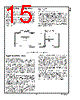
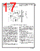
15 / 22 page  LM2507 Features and Operation (Continued) On both the Master and the Slave, the PD* pin resets the logic. The PD* pins should be held low until the power supply has ramped up and is stable and within specifi- cations. Power Down and the use of the PD* Input - When the PD* signal is asserted low, the entire chip regardless of mode, powers down. A Low on the PD* input pin will power down the entire device and turn off the line current to MD0, MD1, and MC. In this state the following outputs are driven to: Master CPU Mode: INTR = Low Slave CPU Mode: DATAn = Low, A/D = CS1* = CS2* = MF0 = MF1 = High Multiple configurations for PowerDown are possible with the chipset. These depend on the operating mode and configu- ration chosen. Two possible applications are shown in Figure 16. In (A) both the Master and Slave provide a PD* input pin. This can be connected together as shown or remotely driven (i.e. a GPO signal from another device, assuming same VDDIO level). However for proper MPL start up, the Slave must be powered up at the same time or before the Master device. Do not power up the Master first. In (B) two separate control signals are used. Note that the Master should not be powered up before the Slave. Application Information SYSTEM CONSIDERATIONS When employing the MPL MST/SLV chipset in place of a parallel bus, a few system considerations must be taken into account. Before sending commands (i.e. initialization com- mands) to the display, the MST/SLV must be ready to trans- mit data across the link. The MPL link must be powered up, and the PLL must be locked. Also a review of the Slave output timing should be completed to insure that the timing parameters provided by the Slave output meet the require- ments of the LCD driver input. Specifically, pulse width on RD* and WR*, data valid time, and bus cycle rate should be reviewed and checked for inter-operability. Additional details are provided next: The MPL link should be started up as follows: The chipset should be powered up first, V DDIO must be powered up first, or it may be at the same time as V DD/VDDA. During power up, the PD* inputs should be held Low and released once power is stable and within specification. The Slave PD* may be released first or at the same time as the Master. CLK should be applied prior to releasing Master PD*. Before data can be sent across the MPL serial link, the link must be ready for transmission. The CLK needs to be ap- plied to the device, and the MST PLL locked. This is con- trolled by a keep-off counter set for 4096 cycles. After the PLL has lock and the counter expired, an additional 540 MC cycles are required for the start-up of the MPL link. After this, data may now be written to the device. It takes 5MC Cycles to send a 16-bit CPU Write including the serial overhead. The MC cycle time is calculated based on the PLL Multiplier of 4X and also the input clock frequency. For example, a 19.2MHz input CLK and a 4X PLLCON setting yields a MC frequency of 76.8MHz. Thus it takes 65.1ns to send the word in serial form. To allow some idle time between transmissions (this will force a bit sync per word if the gap is long enough in between), the load rate on the Master input should not be faster than 6 MC cycles, or every 78ns in our example to support a data pipe line. This is sometimes referred to as the bus cycle time (the time be- tween commands). The Slave output times is also a function of MC cycles. Note that in i80 mode, the width of the WR* pulse low is three MC cycles regardless of the pulse width applied to the Master input. System designers need to check compatibility with the display driver to ensure this pulse width meets its require- ment. If it is too fast, apply a lower input clock frequency. The CLK input must be free running and not gapped. 20186032 FIGURE 15. Power Down Control Options www.national.com 15 |
|
|
リンク URL |
| ALLDATASHEETはお客様のビジネスに役立ちますか? [ DONATE ] |
Alldatasheetは | 広告 | お問い合わせ | プライバシーポリシー | データシートへのリンク | リンク交換 | メーカーリスト All Rights Reserved©Alldatasheet.com |
| Russian : Alldatasheetru.com | Korean : Alldatasheet.co.kr | Spanish : Alldatasheet.es | French : Alldatasheet.fr | Italian : Alldatasheetit.com Portuguese : Alldatasheetpt.com | Polish : Alldatasheet.pl | Vietnamese : Alldatasheet.vn Indian : Alldatasheet.in | Mexican : Alldatasheet.com.mx | British : Alldatasheet.co.uk | New Zealand : Alldatasheet.co.nz |
|
Family Site : ic2ic.com |
icmetro.com |
 Japanese ▼
 English
 Chinese
 German
 Japanese
 Russian
 Korean
 Spanish
 French
 Italian
 Portuguese
 Polish
 Vietnamese
 Indian
 Mexican
 British
 New Zealand