|
データシートサーチシステム |
|
|
データシートサーチシステム |
|
L9908 データシート(PDF) 67 Page - STMicroelectronics |
|
|
|||||||||||||||||||||||||||||
L9908 データシート(HTML) 67 Page - STMicroelectronics |
|
|
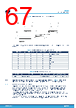
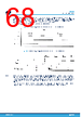
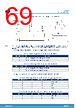
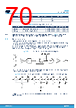
67 / 152 page  Figure 40. Dead Time Protection functional operation The T_dead_flt configuration can be set by the dedicated SPI signal DTP_CFG within the register GEN_CFG1 as follows: Table 61. Dead Time Protection configuration bits DTP_CFG2 DTP_CFG1 DTP_CFG0 Description 0 0 0 0us – DTP Disabled 0 0 1 0.25 μs 0 1 0 0.35 μs 0 1 1 0.5 μs 1 0 0 1 μs – Default 1 0 1 1.5 μs 1 1 0 2 μs 1 1 1 4 μs Table 62. Dead Time Protection accuracy Symbol Parameter Test Condition Min Typ Max Unit DTP_tflt_acc Dead Time Filter accuracy CLK_SSM_EN = 0 -15 15 % Note: All parameters are guaranteed, and tested, in the voltage ranges reported above in Table 5 unless otherwise specified. Where not specified the parametrical operating range equals the functional operating range. 5.12.3 Shoot-Through Protection (STP) Independently of the activation of DTP, L9908 implements a monitoring unit to detect the dangerous condition when HS and LS of the same half bridge are driven on at the same time. The diagnosis is performed at two levels: on the devices PWM inputs from uC (INHn/INLn) and on the Ext. FET Vgs; this allows a diagnosis coverage both on external and internal shoot-through faults. The first diagnosis level consists in a dedicated digital counter for each half bridge PWM inputs (INHn/INLn couple) set/reset by the logic AND between INHn and INLn and integrates the time interval where the INHn and the INLn are high together. If INHn=INLn=’1’ occurs for an interval longer than T_stp_pwm_flt the flag STP_PWM_n is set. The error flag remains set until the failure condition is removed and the flag is cleared by the SPI command. L9908 Functional description DS13546 - Rev 5 page 67/152 |
|
リンク URL |
| ALLDATASHEETはお客様のビジネスに役立ちますか? [ DONATE ] |
Alldatasheetは | 広告 | お問い合わせ | プライバシーポリシー | データシートへのリンク | リンク交換 | メーカーリスト All Rights Reserved©Alldatasheet.com |
| Russian : Alldatasheetru.com | Korean : Alldatasheet.co.kr | Spanish : Alldatasheet.es | French : Alldatasheet.fr | Italian : Alldatasheetit.com Portuguese : Alldatasheetpt.com | Polish : Alldatasheet.pl | Vietnamese : Alldatasheet.vn Indian : Alldatasheet.in | Mexican : Alldatasheet.com.mx | British : Alldatasheet.co.uk | New Zealand : Alldatasheet.co.nz |
|
Family Site : ic2ic.com |
icmetro.com |
 Japanese ▼
 English
 Chinese
 German
 Japanese
 Russian
 Korean
 Spanish
 French
 Italian
 Portuguese
 Polish
 Vietnamese
 Indian
 Mexican
 British
 New Zealand