|
データシートサーチシステム |
|
|
データシートサーチシステム |
|
MCP3901A2T-I/SS データシート(PDF) 35 Page - Microchip Technology |
|
|
|||||||||||||||||||||||||||||
MCP3901A2T-I/SS データシート(HTML) 35 Page - Microchip Technology |
|
|
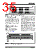
35 / 60 page  © 2009 Microchip Technology Inc. DS22192A-page 35 MCP3901 FIGURE 6-5: Device Write (SPI Mode 0,0 - Clock Idles Low). 6.7 Continuous Communication, Looping On Address Sets If the user wishes to read back either of the ADC channels continuously, or both channels continuously, the internal address counter of the MCP3901 can be set to loop on specific register sets. In this case, there is only one control byte on SDI to start the communication. The part stays within the same loop until CS returns high. This internal address counter allows the following functionality: • Read one ADC channel data continuously • Read both ADC channel data continuously (both ADC data can be independent or linked with DRMODE settings) • Read continuously the entire register map • Read continuously each separate register • Read continuously all configuration registers • Write all configuration registers in one communication (see Figure 6-6) The STATUS/COM register contains the loop settings for the internal address counter (READ<1:0>). The internal address counter can either stay constant (READ<1:0>=00) and read continuously the same byte, or it can auto-increment and loop through the register groups defined below (READ<1:0>=01), register types (READ<1:0>=10) or the entire register map (READ<1:0>=11). Each channel is configured independently as either a 16-bit or 24-bit data word depending on the setting of the corresponding WIDTH bit in the CONFIG1 register. For continuous reading, in the case of WIDTH=0 (16-bit), the lower byte of the ADC data is not accessed and the part jumps automatically to the following address (the user does not have to clock out the lower byte since it becomes undefined for WIDTH=0). The following figure represents a typical continuous read communication with the default settings (DRMODE<1:0>=00, READ<1:0>=10) for both WIDTH settings. This configuration is typically used for power metering applications. FIGURE 6-6: Typical Continuous Read Communication. SCK SDI SDO CS R/W A6 A5 A4 A3 A2 A1 A0 D7 D6 D5 D4 D3 D2 D1 D7 (ADDRESS) DATA (ADDRESS + 1) DATA D6 D5 D4 D3 D2 D1 D7 OF (ADDRESS + 2) DATA D0 Data Transitions on the Falling Edge MCU and MCP3901 Latch Bits on the Rising Edge D0 HI-Z HI-Z HI-Z CH0 ADC ADDR/R CS SCK SDI CH0 ADC Upper byte SDO CH0 ADC Middle byte CH0 ADC Lower byte DR CH1 ADC Upper byte CH1 ADC Middle byte CH1 ADC Lower byte CH0 ADC Upper byte CH0 ADC Middle byte CH0 ADC Lower byte CH1 ADC Upper byte CH1 ADC Middle byte CH1 ADC Lower byte These bytes are not present when WIDTH=0 (16-bit mode) |
|
リンク URL |
| ALLDATASHEETはお客様のビジネスに役立ちますか? [ DONATE ] |
Alldatasheetは | 広告 | お問い合わせ | プライバシーポリシー | データシートへのリンク | リンク交換 | メーカーリスト All Rights Reserved©Alldatasheet.com |
| Russian : Alldatasheetru.com | Korean : Alldatasheet.co.kr | Spanish : Alldatasheet.es | French : Alldatasheet.fr | Italian : Alldatasheetit.com Portuguese : Alldatasheetpt.com | Polish : Alldatasheet.pl | Vietnamese : Alldatasheet.vn Indian : Alldatasheet.in | Mexican : Alldatasheet.com.mx | British : Alldatasheet.co.uk | New Zealand : Alldatasheet.co.nz |
|
Family Site : ic2ic.com |
icmetro.com |
 Japanese ▼
 English
 Chinese
 German
 Japanese
 Russian
 Korean
 Spanish
 French
 Italian
 Portuguese
 Polish
 Vietnamese
 Indian
 Mexican
 British
 New Zealand