|
データシートサーチシステム |
|
|
データシートサーチシステム |
|
MPC5121E データシート(PDF) 64 Page - Freescale Semiconductor, Inc |
|
|
|||||||||||||||||||||||||||||
MPC5121E データシート(HTML) 64 Page - Freescale Semiconductor, Inc |
|
|
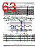
64 / 86 page  MPC5121E/MPC5123 Data Sheet, Rev. 1 Electrical and Thermal Characteristics Freescale Semiconductor 64 3.3.16 SPDIF The Sony/Philips Digital Interface (SPDIF) timing is totally asynchronous, therefore there is no need for relationship with the clock. 3.3.17 CAN The CAN functions are available as TX pins at normal IO pads and as RX pins at the VBAT_RTC domain. There is no filter for the WakeUp dominant pulse. Any High-to-Low edge can cause WakeUp, if configured. 3.3.18 I2C This section specifies the timing parameters of the Inter-Integrated Circuit (I2C) interface. Refere to the I2C-Bus Specification. Table 39. I2C Input Timing Specifications – SCL and SDA Sym Description Min Max Units SpecID 1 Start condition hold time 2 — IP-Bus Cycle1 1 Inter Peripheral Clock is defined in the MPC5121e/MPC5123 Reference Manual. A18.1 2 Clock low time 8 — IP-Bus Cycle1 A18.2 4 Data hold time 0.0 — ns A18.3 6 Clock high time 4 — IP-Bus Cycle1 A18.4 7 Data setup time 0.0 — ns A18.5 8 Start condition setup time (for repeated start condition only) 2 — IP-Bus Cycle1 A18.6 9 Stop condition setup time 2 — IP-Bus Cycle1 A18.7 Table 40. I2C Output Timing Specifications – SCL and SDA Sym Description Min Max Units SpecID 11 1 Programming IFDR with the maximum frequency results in the minimum output timings listed. The I2C interface is designed to scale the data transition time, moving it to the middle of the SCL low period. The actual position is affected by the prescale and division values programmed in IFDR. Start condition hold time 6 — IP-Bus Cycle2 2 Because SCL and SDA are open-drain-type outputs, which the processor can only actively drive low, the time SCL or SDA takes to reach a high level depends on external signal capacitance and pull-up resistor values A18.8 21 Clock low time 10 — IP-Bus Cycle2 A18.9 33 SCL/SDA rise time — 7.9 ns A18.10 41 Data hold time 7 — IP-Bus Cycle2 A18.11 51 SCL/SDA fall time — 7.9 ns A18.12 61 Clock high time 10 — IP-Bus Cycle2 A18.13 71 Data setup time 2 — IP-Bus Cycle2 A18.14 81 Start condition setup time (for repeated start condition only) 20 — IP-Bus Cycle2 A18.15 91 Stop condition setup time 10 — IP-Bus Cycle2 A18.16 Preliminary |
|
リンク URL |
| ALLDATASHEETはお客様のビジネスに役立ちますか? [ DONATE ] |
Alldatasheetは | 広告 | お問い合わせ | プライバシーポリシー | データシートへのリンク | リンク交換 | メーカーリスト All Rights Reserved©Alldatasheet.com |
| Russian : Alldatasheetru.com | Korean : Alldatasheet.co.kr | Spanish : Alldatasheet.es | French : Alldatasheet.fr | Italian : Alldatasheetit.com Portuguese : Alldatasheetpt.com | Polish : Alldatasheet.pl | Vietnamese : Alldatasheet.vn Indian : Alldatasheet.in | Mexican : Alldatasheet.com.mx | British : Alldatasheet.co.uk | New Zealand : Alldatasheet.co.nz |
|
Family Site : ic2ic.com |
icmetro.com |
 Japanese ▼
 English
 Chinese
 German
 Japanese
 Russian
 Korean
 Spanish
 French
 Italian
 Portuguese
 Polish
 Vietnamese
 Indian
 Mexican
 British
 New Zealand