|
データシートサーチシステム |
|
|
データシートサーチシステム |
|
MCP6V06T データシート(PDF) 24 Page - Microchip Technology |
|
|
|||||||||||||||||||||||||||||
MCP6V06T データシート(HTML) 24 Page - Microchip Technology |
|
|
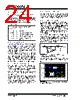
24 / 44 page  MCP6V06/7/8 DS22093B-page 24 © 2008 Microchip Technology Inc. 4.3 Application Tips 4.3.1 INPUT OFFSET VOLTAGE OVER TEMPERATURE Table 1-1 gives both the linear and quadratic tempera- ture coefficients (TC1 and TC2) of input offset voltage. The input offset voltage, at any temperature in the specified range, can be calculated as follows: EQUATION 4-1: 4.3.2 DC GAIN PLOTS Figure 2-9, Figure 2-10 and Figure 2-11 are histograms of the reciprocals (in units of µV/V) of CMRR, PSRR and AOL, respectively. They represent the change in input offset voltage (VOS) with a change in common mode input voltage (VCM), power supply voltage (VDD) and output voltage (VOUT). The 1/AOL histogram is centered near 0 µV/V because the measurements are dominated by the op amp’s input noise. The negative values shown represent noise, not unstable behavior. We validate the op amps’ stability by making multiple measurements of VOS; instability would manifest itself as a greater unex- plained variability in VOS or as the railing of the output. 4.3.3 SOURCE RESISTANCES The input bias currents have two significant components; switching glitches that dominate at room temperature and below, and input ESD diode leakage currents that dominate at +85°C and above. Make the resistances seen by the inputs small and equal. This minimizes the output offset caused by the input bias currents. The inputs should see a resistance on the order of 10 Ω to 1 k Ω at high frequencies (i.e., above 1 MHz). This helps minimize the impact of switching glitches, which are very fast, on overall performance. In some cases, it may be necessary to add resistors in series with the inputs to achieve this improvement in performance. 4.3.4 SOURCE CAPACITANCE The capacitances seen by the two inputs should be small and matched. The internal switches connected to the inputs dump charges on these capacitors; an offset can be created if the capacitances do not match. 4.3.5 CAPACITIVE LOADS Driving large capacitive loads can cause stability problems for voltage feedback op amps. As the load capacitance increases, the feedback loop’s phase margin decreases and the closed-loop bandwidth is reduced. This produces gain peaking in the frequency response, with overshoot and ringing in the step response. These auto-zeroed op amps have a different output impedance than most op amps, due to their unique topology. When driving a capacitive load with these op amps, a series resistor at the output (RISO in Figure 4-6) improves the feedback loop’s phase margin (stability) by making the output load resistive at higher frequen- cies. The bandwidth will be generally lower than the bandwidth with no capacitive load. FIGURE 4-6: Output Resistor, RISO, Stabilizes Capacitive Loads. Figure 4-7 gives recommended RISO values for different capacitive loads and is independent of the gain. FIGURE 4-7: Recommended RISO values for Capacitive Loads. V OS TA () V OS TC 1ΔTTC2ΔT 2 ++ = Where: ΔT=TA –25°C VOS(TA) = input offset voltage at TA VOS = input offset voltage at +25°C TC1 = linear temperature coefficient TC2 = quadratic temperature coefficient RISO CL VOUT MCP6V0X 10 100 1000 10000 1.E-12 1.E-11 1.E-10 1.E-09 1.E-08 1.E-07 CL (F) 1p 10p 100p 1n 10n 100n 10 100 1k 10k GN < 2 GN = 5 GN = 10 |
|
リンク URL |
| ALLDATASHEETはお客様のビジネスに役立ちますか? [ DONATE ] |
Alldatasheetは | 広告 | お問い合わせ | プライバシーポリシー | データシートへのリンク | リンク交換 | メーカーリスト All Rights Reserved©Alldatasheet.com |
| Russian : Alldatasheetru.com | Korean : Alldatasheet.co.kr | Spanish : Alldatasheet.es | French : Alldatasheet.fr | Italian : Alldatasheetit.com Portuguese : Alldatasheetpt.com | Polish : Alldatasheet.pl | Vietnamese : Alldatasheet.vn Indian : Alldatasheet.in | Mexican : Alldatasheet.com.mx | British : Alldatasheet.co.uk | New Zealand : Alldatasheet.co.nz |
|
Family Site : ic2ic.com |
icmetro.com |
 Japanese ▼
 English
 Chinese
 German
 Japanese
 Russian
 Korean
 Spanish
 French
 Italian
 Portuguese
 Polish
 Vietnamese
 Indian
 Mexican
 British
 New Zealand