|
データシートサーチシステム |
|
|
データシートサーチシステム |
|
ISL73847SEHDEMO2Z データシート(PDF) 27 Page - Renesas Technology Corp |
|
|
|||||||||||||||||||||||||||||
ISL73847SEHDEMO2Z データシート(HTML) 27 Page - Renesas Technology Corp |
|
|
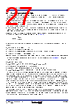
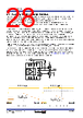
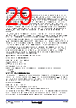
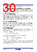
27 / 40 page  R34DS0017EU0104 Rev.1.04 Page 27 Jan 31, 2025 ISL73041SEH Datasheet 6.9 Bootstrap Capacitor Design The high-side bootstrap capacitor provides the bias to the floating high-side circuitry to drive the high-side FET. The bootstrap capacitor recharges to PVCC voltage when the boot switch turns on. Choose the bootstrap capacitor to satisfy two conditions. ▪ It should be large enough to provide for the high-side driver bias current, the high-side driver DC output current (primarily the 1kΩ resistor on UGL to PHS), the high-side FET gate leakage current, and the instantaneous current to turn on the high-side FET (provide the gate charge) during the high-side on switching period, without discharging the boot voltage significantly. ▪ It should be small enough such that at initial start-up, the boot-refresh time meets system requirements. The resistance of the boot switch and the bootstrap capacitance determines the initial boot refresh to charge the boot capacitor from 0V to PVCC. A good starting point is to design for a 5% discharge of the boot voltage during steady-state operation of the high-side drive. To determine the bootstrap capacitor, use Equation 4. where QTOT is total charge require to operate the high-side driver during high-side on-time. QTOT includes the following: ▪ Gate charge for the high-side FET turn-on. ▪ Charge for the high-side driver boot bias current. ▪ Charge for the high-side gate-source resistor when driver is sourcing BOOT voltage. ▪ Charge for the high-side FET gate leakage current. VDROP is the amount of voltage drop across the boot capacitor. For PVCC = 4.5V: VDROP = 4.5V × 0.05 = 225mV. The following is a design example of a 12V to 1V DC/DC converter at 500kHz using ISL70023SEH 100V GaN FET as the high-side FET: ▪ QGS1 = 25nC gate charge ▪ IBOOT = 600µA; tON = 1V/12V × 2µs = 167ns; QBOOT = IBOOT × tON = 0.1nC ▪ For 4.5V gate drive, QGS2 = 4.5V/1kΩ × 167ns = 0.75nC ▪ ISL70023SEH specifies 9mA gate leakage. QLEAK = 9mA × 167ns = 1.5nC ▪ CBOOT = QTOT/VDROP = 27.4nC / 225mV = 122nF (Use 100nF or 150nF standard value) This capacitor is the minimum recommended bootstrap capacitor value to meet ripple voltage. Also, it is important to size the capacitor appropriately. During system start-up, the bootstrap capacitor is at 0V. The PWM controller must issue a boot refresh for the high-side driver to clear BOOT UVLO and have sufficient boot bias. Otherwise, the first few high-side commands do not turn on the upper FET, potentially causing system faults. The bootstrap capacitor is charged through PVCC and the internal 1Ω typical boot switch, forming an RC circuit. The boot refresh command from the PWM controller must drive PWM = 0V, and PHS must be within 250mV of PGND to turn on the boot switch and charge the capacitor. The boot refresh command needs to be of long enough duration for the RC circuit to charge above the BOOT UVLO threshold and maintain boot voltage in operation (for example, t = 3×RC would charge the capacitor to 95% of the final voltage). With a 1Ω boot switch impedance and 150nF bootstrap capacitor, this would require a boot refresh time of 450ns. The ISL73847SEH PWM controller includes a built-in boot refresh command before a soft start-up during initial power-up and recovery from a hiccup. The controller issues 32 pulses of PWM switching between 0V (logic low) and 2V (mid-level). The oscillator of the ISL73847SEH controller sets the boot refresh pulse frequency and has a typical 100ns refresh time (PWM = 0V) to charge the boot capacitor. (EQ. 4) CBOOT QTOT VDROP -------------------- = |
|
リンク URL |
| ALLDATASHEETはお客様のビジネスに役立ちますか? [ DONATE ] |
Alldatasheetは | 広告 | お問い合わせ | プライバシーポリシー | データシートへのリンク | リンク交換 | メーカーリスト All Rights Reserved©Alldatasheet.com |
| Russian : Alldatasheetru.com | Korean : Alldatasheet.co.kr | Spanish : Alldatasheet.es | French : Alldatasheet.fr | Italian : Alldatasheetit.com Portuguese : Alldatasheetpt.com | Polish : Alldatasheet.pl | Vietnamese : Alldatasheet.vn Indian : Alldatasheet.in | Mexican : Alldatasheet.com.mx | British : Alldatasheet.co.uk | New Zealand : Alldatasheet.co.nz |
|
Family Site : ic2ic.com |
icmetro.com |
 Japanese ▼
 English
 Chinese
 German
 Japanese
 Russian
 Korean
 Spanish
 French
 Italian
 Portuguese
 Polish
 Vietnamese
 Indian
 Mexican
 British
 New Zealand